
Videos
For the op−amp in the voltage follower circuit in Figure P14.14, the open−loop parameters are
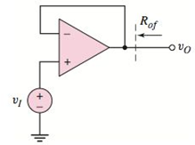
Figure P14.14
Want to see the full answer?
Check out a sample textbook solution
Chapter 14 Solutions
Microelectronics: Circuit Analysis and Design


- Using a positive Clamper Circuit, with an AC voltage of Vi = 13v with a frequency of 60hz, a value of 100u for the Capacitor, a silicon diode and a resistor with the value of 1000 ohms. Find the voltage value on the resistor at a simulation of 20ms. 2Vm Vm Vm Vo -Vm Input Waveform Output Waveform Positive Clamper circuitarrow_forwardC'uk Converter Design A C'uk converter has an input of 12 V and is to have an output of - 24 V supplying a 60 W load. Select the duty ratio, the switching frequency, the inductor sizes such that the change in inductor currents is no more than 12 percent of the average inductor current, the output ripple voltage is no more than 1.5 percent, and the ripple voltage across C1 is no more than 3 percent.arrow_forwardFor the following zener clipper draw the output waveform Vz1 = 5V, Vz1 = 7V VK = 0.8v lkn ISV V₁₂ 5V 2, 72. -5V Q2 Determine The Output Waveform And Calculate The current and PIV 1kQ 1kQ 10 V 10 si www www Q. For the circuit shown in Figure below (1),find the maximum and minimum values of zener diod current. Live 5 ΚΩ www I IL 15 80-120 V 10 ΚΩ LIR 101 102 1015 S Ne 1 k0 www Iz 50 V U2 -ot V. Fumal inasharrow_forward
- 2. The circuit given below is using a transformer of 230V/30V. The load resistance is 10KS. Find Vin (rms and peak values), Vdiode and VLOAD (Peak and dc values). Draw the input and output voltage waveforms. (Si diode) Vin: Vin rms= Vin peak = VDIODE Vdiode = 4 Vin VLOAD: VLOAD Peak =. Load VLOAD VLOAD DC= 2031 Supply wwwwwwarrow_forwardIn the full-wave rectifier circuit of figure, the transformer has a turns ratio of 1:2. The transformer primary winding is connected across an AC source of 230V (rms), 50 Hz. The load resistor is 50ohms. For this circuit, determine the peak-to- peak ripple in the output voltage * Di i v2 = VmSin ot RL Vs(N V1 Vo + V3 = VmSin ot D2 Full-wave rectifier- Circuit operation during positive half cycle 460 V 207 V 325.3 V None of the above ell ellarrow_forwardFor the given circuit below, it operates on a peak- to-peak input voltage of 112.3 V, F = 60 Hz household supply through a step-down transformer with turns N1 = 10 and N2 = 1. Silicon diodes are used with a 1 Kiloohms load. Determine the output peak voltage (in volts). D1 D2 AC Input Vsec (source) D3 .... D4 Load 4.21 4.01 7.86 7.02 elllearrow_forward
- A step down converter is operated with a duty cycle of k = 0.75. The input voltage is Vs = 20V, and the load is: L = 5mH, R = 1502. The minimum inductor current is I₁ = 0.1A. The maximum inductor current is: Select one: a. 1.9 A b. None of these OC. 0.9 A O d. 1.1 A Oe. 2 Aarrow_forwardFor clipper circuit shown below vs = 5sin(wt) and Vs=2V the output will be : V(t) R. Ideal Diode V. O a. Same AC input but clipping at +2V Ob. Same AC input but clipping at -2V O C. No clipping O d. DC +2 V output onlyarrow_forwardSignal subject 2arrow_forward
- Q4) Determine and sketch the output voltage across the load resistor (RL) for the circuit shown below (assume Si diodes) V_DC V DC 0,75 (1+ 0.25 V_SIN V SIN RL -1 V SOR V_SQR 0.75 -0.75 V TRI 1 V_TRI -1arrow_forwardCalculate the peak-to-peak inductor current ripple (in amperes) of a Buck converter assuming it operates in continuous current conduction mode. Circuit parameters are: Input voltage Vdc = 38 V, output voltage Vo = 17 V, PWM frequency fpwm = 50 kHz, inductor value 328 µH and capacitor value C = 10 µF. is S iL L I₂ Vac VA D VL ic C R₁ Please specify your answer in units of A to 2 decimal places. Varrow_forwardQ2:-Find the output voltage Vo . Ry B2HF 100 kQ + 100 mV rms,arrow_forward
 Introductory Circuit Analysis (13th Edition)Electrical EngineeringISBN:9780133923605Author:Robert L. BoylestadPublisher:PEARSON
 Delmar's Standard Textbook Of ElectricityElectrical EngineeringISBN:9781337900348Author:Stephen L. HermanPublisher:Cengage Learning
 Programmable Logic ControllersElectrical EngineeringISBN:9780073373843Author:Frank D. PetruzellaPublisher:McGraw-Hill Education
 Fundamentals of Electric CircuitsElectrical EngineeringISBN:9780078028229Author:Charles K Alexander, Matthew SadikuPublisher:McGraw-Hill Education
 Electric Circuits. (11th Edition)Electrical EngineeringISBN:9780134746968Author:James W. Nilsson, Susan RiedelPublisher:PEARSON
 Engineering ElectromagneticsElectrical EngineeringISBN:9780078028151Author:Hayt, William H. (william Hart), Jr, BUCK, John A.Publisher:Mcgraw-hill Education,