
Fundamentals of Electric Circuits
6th Edition
ISBN: 9780078028229
Author: Charles K Alexander, Matthew Sadiku
Publisher: McGraw-Hill Education
expand_more
expand_more
format_list_bulleted
Concept explainers
Videos
Textbook Question
Chapter 13, Problem 36P
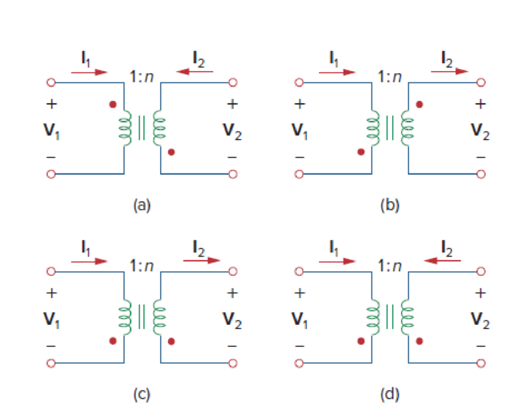
As done in Fig. 13.33, obtain the relationships between terminal voltages and currents for each of the ideal transformers in Fig. 13.105.
Expert Solution & Answer
Want to see the full answer?
Check out a sample textbook solution
Students have asked these similar questions
The primary of a current transformer takes 1 A at a power factor of 0.4 when it is connected across a 200-V, 50Hz supply and the secondary is on open circuit. The number of turns on the primary is twice that on the secondary. A load taking 50 A at a lagging power factor of 0.8 is now connected across the secondary. What is now the value of primary current?
a device has an average power rating of 1200W and deisgn to operate 250V rms line. detrmine the effective resistance if the power socket available has 115V rms line and uses a step up ideal transformer from 115V to 250V.
Please answer the question step by step and please care to explain the question in detailed with your own sentence and explain why you used that formula, calculations etc asap. Thanks in advance.
Chapter 13 Solutions
Fundamentals of Electric Circuits
Ch. 13.2 - Determine the voltage Vo in the circuit of Fig....Ch. 13.2 - Determine the phasor currents I1 and I2 in the...Ch. 13.3 - Prob. 3PPCh. 13.4 - Find the input impedance of the circuit in Fig....Ch. 13.4 - For the linear transformer in Fig. 13.26(a), find...Ch. 13.4 - Solve the problem in Example 13.1 (see Fig. 13.9)...Ch. 13.5 - The primary current to an ideal transformer rated...Ch. 13.5 - In the ideal transformer circuit of Fig. 13.38,...Ch. 13.5 - Find Vo in the circuit of Fig. 13.40. Figure 13.40...Ch. 13.6 - Refer to Fig. 13.43. If the two-winding...
Ch. 13.6 - In the autotransformer circuit of Fig. 13.45, find...Ch. 13.7 - Prob. 12PPCh. 13.8 - Prob. 13PPCh. 13.9 - Refer to Fig. 13.61. Calculate the turns ratio...Ch. 13.9 - Calculate the turns ratio of an ideal transformer...Ch. 13.9 - In Example 13.17, if the eight 100-W bulbs are...Ch. 13 - Refer to the two magnetically coupled coils of...Ch. 13 - Prob. 2RQCh. 13 - Prob. 3RQCh. 13 - Prob. 4RQCh. 13 - The ideal transformer in Fig. 13.70(a) has N2/N1 =...Ch. 13 - Prob. 6RQCh. 13 - A three-winding transformer is connected as...Ch. 13 - Prob. 8RQCh. 13 - Prob. 9RQCh. 13 - Prob. 10RQCh. 13 - For the three coupled coils in Fig. 13.72,...Ch. 13 - Using Fig. 13.73, design a problem to help other...Ch. 13 - Two coils connected in series-aiding fashion have...Ch. 13 - (a) For the coupled coils in Fig. 13.74(a), show...Ch. 13 - Two coils are mutually coupled, with L1 = 50 mH,...Ch. 13 - Given the circuit shown in Fig. 13.75, determine...Ch. 13 - For the circuit in Fig. 13.76, find Vo. Figure...Ch. 13 - Find v(t) for the circuit in Fig. 13.77.Ch. 13 - Prob. 9PCh. 13 - Find vo in the circuit of Fig. 13.79. Figure 13.79...Ch. 13 - Use mesh analysis to find ix in Fig. 13.80, where...Ch. 13 - Determine the equivalent Leq in the circuit of...Ch. 13 - For the circuit in Fig. 13.82, determine the...Ch. 13 - Obtain the Thevenin equivalent circuit for the...Ch. 13 - Find the Norton equivalent for the circuit in Fig....Ch. 13 - Obtain the Norton equivalent at terminals a-b of...Ch. 13 - In the circuit of Fig. 13.86, ZL is a 15-mH...Ch. 13 - Find the Thevenin equivalent to the left of the...Ch. 13 - Determine an equivalent T-section that can be used...Ch. 13 - Determine currents I1, I2, and I3 in the circuit...Ch. 13 - Prob. 21PCh. 13 - Find current Io in the circuit of Fig. 13.91.Ch. 13 - Let is = 5 cos (100t) A. Calculate the voltage...Ch. 13 - In the circuit of Fig. 13.93, (a) find the...Ch. 13 - Prob. 25PCh. 13 - Find Io in the circuit of Fig. 13.95. Switch the...Ch. 13 - Find the average power delivered to the 50-...Ch. 13 - In the circuit of Fig. 13.97, find the value of X...Ch. 13 - Prob. 29PCh. 13 - (a) Find the input impedance of the circuit in...Ch. 13 - Using Fig. 13.100, design a problem to help other...Ch. 13 - Two linear transformers are cascaded as shown in...Ch. 13 - Determine the input impedance of the air-core...Ch. 13 - Using Fig. 13.103, design a problem to help other...Ch. 13 - Find currents I1, I2, and I3 in the circuit of...Ch. 13 - As done in Fig. 13.33, obtain the relationships...Ch. 13 - A 2402,400-V rms step-up ideal transformer...Ch. 13 - Design a problem to help other students better...Ch. 13 - A 1,200240-V rms transformer has impedance on the...Ch. 13 - The primary of an ideal transformer with a turns...Ch. 13 - Given I2 = 2 A, determine the value of Is in Fig....Ch. 13 - For the circuit in Fig. 13.107, determine the...Ch. 13 - Obtain V1 and V2 in the ideal transformer circuit...Ch. 13 - In the ideal transformer circuit of Fig. 13.109,...Ch. 13 - For the circuit in Fig. 13.110, find the value of...Ch. 13 - (a) Find I1 and I2 in the circuit of Fig. 13.111...Ch. 13 - Prob. 47PCh. 13 - Using Fig. 13.113, design a problem to help other...Ch. 13 - Find current ix in the ideal transformer circuit...Ch. 13 - Prob. 50PCh. 13 - Use the concept of reflected impedance to find the...Ch. 13 - For the circuit in Fig. 13.117, determine the...Ch. 13 - Refer to the network in Fig. 13.118. (a) Find n...Ch. 13 - A transformer is used to match an amplifier with...Ch. 13 - For the circuit in Fig. 13.120, calculate the...Ch. 13 - Find the power absorbed by the 100- resistor in...Ch. 13 - For the ideal transformer circuit of Fig. 13.122...Ch. 13 - Determine the average power absorbed by each...Ch. 13 - In the circuit of Fig. 13.124, let vs = 165...Ch. 13 - Refer to the circuit in Fig. 13.125 on the...Ch. 13 - For the circuit in Fig. 13.126, find Il, I2, and...Ch. 13 - For the network in Fig. 13.127, find: (a) the...Ch. 13 - Find the mesh currents in th circuit of Fig....Ch. 13 - For the circuit in Fig. 13.129. find the turns...Ch. 13 - Calculate the average power dissipated by the 20-...Ch. 13 - Design a problem to help other students better...Ch. 13 - An autotransformer with a 40 percent tap is...Ch. 13 - In the ideal autotransformer of Fig. 13.131,...Ch. 13 - In the circuit of Fig. 13.131, N1 = 190 turns and...Ch. 13 - In the ideal transformer circuit shown in Fig....Ch. 13 - When individuals travel, their electrical...Ch. 13 - In order to meet an emergency, three single-phase...Ch. 13 - Figure 13.135 on the next page shows a three-phase...Ch. 13 - Consider the three-phase transformer shown in Fig....Ch. 13 - A balanced three-phase transformer bank with the...Ch. 13 - Using Fig. 13.138, design a problem to help other...Ch. 13 - The three-phase system of a town distributes power...Ch. 13 - Use PSpice or MultiSim to determine the mesh...Ch. 13 - Use PSpice or MultiSim to find I1, I2, and I3 in...Ch. 13 - Prob. 80PCh. 13 - Use PSpice or MultiSim to find I1, I2, and I3 in...Ch. 13 - A stereo amplifier circuit with ail output...Ch. 13 - A transformer having 2,400 turns on the primary...Ch. 13 - A radio receiver has an input resistance of 300 ....Ch. 13 - A step-down power transformer with a turns ratio...Ch. 13 - A 240120-V rms power transformer is rated at 10...Ch. 13 - A 4-kVA, 2,400240-V rms transformer has 250 turns...Ch. 13 - A 25,000240-V rms distribution transformer has a...Ch. 13 - A 4,800-V rms transmission line feeds a...Ch. 13 - A four-winding transformer (Fig. 13.146) is often...Ch. 13 - A 440/110-V ideal transformer can be connected to...Ch. 13 - Ten bulbs in parallel are supplied by a 7,200120-V...
Additional Engineering Textbook Solutions
Find more solutions based on key concepts
CONCEPT QUESTIONS
15.CQ3 The ball rolls without slipping on the fixed surface as shown. What is the direction ...
Vector Mechanics for Engineers: Statics and Dynamics
How are relationships between tables expressed in a relational database?
Modern Database Management
How is the hydrodynamic entry length defined for flow in a pipe? Is the entry length longer in laminar or turbu...
Fluid Mechanics: Fundamentals and Applications
The following C++ program will not compile because the lines have been mixed up. cout Success\n; cout Success...
Starting Out with C++ from Control Structures to Objects (9th Edition)
Assume a telephone signal travels through a cable at two-thirds the speed of light. How long does it take the s...
Electric Circuits. (11th Edition)
The solid steel shaft AC has a diameter of 25 mm and is supported by smooth bearings at D and E. It is coupled ...
Mechanics of Materials (10th Edition)
Knowledge Booster


Learn more about
Need a deep-dive on the concept behind this application? Look no further. Learn more about this topic, electrical-engineering and related others by exploring similar questions and additional content below.Similar questions
- An ideal auto-transformer has its secondary winding labelled as a, b and c. The primary winding has 100 turns. The number of turns on the secondary side are 400 turns between a and b and 200 turns between b and c. The total number of turns between a and c is 600 turns. The transformer supplies a resistive load of 6 kW between a and c. In addition, a load of impedance 1,000 cis (45°) ohms is connected between a and b. For a primary voltage of 1,000 V, find the primary current and primary input power.arrow_forwardThe primary resistance of a 440/110-V transformer is 0.5 ohms and the secondary resistance is 0.04 ohms. When 440 V is applied to the primary and secondary is left open-circuited, 200 W is drawn from the supply. Find the secondary current which will give maximum efficiency and calculate this efficiency for a load having unity power factor.arrow_forwardA three phase converter has a rating of 600 kW when operating at unity power factor. Neglecting any change in efficiency, what would be its rating when operating at a power factor of 0.85. (ILLUSTRATIONS such as diagrams and graphs are Required).arrow_forward
- An ideal transformer 2,400/240 V has a certain load of 50 A, unity power factor which is to be connected to the low voltage winding. This load must have exactly 200 V across it. With 2,400 V applied to the high voltage winding, what resistance must be added in series with the transformer at the low voltage winding?arrow_forwardIs it possible have some help with this question, I get 75v for secondary emf and 0.5amps as secondary current!! thanksarrow_forwardQ1) A 20KVA , 2000/200 V single phase ,50 Hz transformer has a primary resistance of 2.5 0 and reactance of 4.8 Q .the secondary resistance and reactance are 0.01 Q and 0.018 0 respectively .find a- equivalent resistance ,reactance and impedance referred to primary. b- equivalent resistance ,reactance and impedance referred to secondary.arrow_forward
- A 230/460-V transformer has a primary resistance of 0.2 ohms and reactance of 0.5 ohms and the corresponding values for the secondary are 0.75 ohms and 1.8 ohms respectively. Find the secondary terminal voltage when supplying 15 A at 0.6 pf lagging.arrow_forwardSubject: Circuits IIIf the secondary of the transformer is step down, the primary will havearrow_forwardProblem 1 The primary resistance of a 440/110-V transformer is 0.50 and the secondary resistance is 0.04 02. When 440 V is applied to the primary and secondary is left open-circuited, 200 W is drawn from the supply. Find the secondary current which will give maximum efficiency and calculate this efficiency for a load having unity power factor.arrow_forward
- Approximate solution time is 5 minutes. A transformer supplies power to a feeder that has five customers. Daily maximum demands for these customers are 120 kW, 40 kW, 90 kW, 110 kW, and 180kW. The maximum demand on the feeder is 243kW. The coincident factor of the feeder isarrow_forward9- While conducting short-circuit test on a transformer the following side is short- circuited a) - H.V side , b) - Secondary side c) - L.V side d) - primary side 10- The power factor of a transformer on no load will be about a)- unity b)-o.75 c)- 0.5 d)- 0.35arrow_forwardYou have been assigned to select a transformer to supply a peak power of 100 kW to a load that draws peak power only a very small percentage of the time and draws very little power the rest of the time. Two transformers, A and B, are both suitable. While both transformers have the same efficiency at peak load, most of the loss in A is due to core loss, and most of the loss in B is due to the resistances of the coils. From the standpoint of operating costs, which transformer is better? Why?arrow_forward
arrow_back_ios
SEE MORE QUESTIONS
arrow_forward_ios
Recommended textbooks for you
 Power System Analysis and Design (MindTap Course ...Electrical EngineeringISBN:9781305632134Author:J. Duncan Glover, Thomas Overbye, Mulukutla S. SarmaPublisher:Cengage Learning
Power System Analysis and Design (MindTap Course ...
Electrical Engineering
ISBN:9781305632134
Author:J. Duncan Glover, Thomas Overbye, Mulukutla S. Sarma
Publisher:Cengage Learning
TRANSFORMERS - What They Are, How They Work, How Electricians Size Them; Author: Electrician U;https://www.youtube.com/watch?v=tXPy4OE7ApE;License: Standard Youtube License