
Fundamentals of Electric Circuits
6th Edition
ISBN: 9780078028229
Author: Charles K Alexander, Matthew Sadiku
Publisher: McGraw-Hill Education
expand_more
expand_more
format_list_bulleted
Concept explainers
Videos
Textbook Question
Chapter 13, Problem 54P
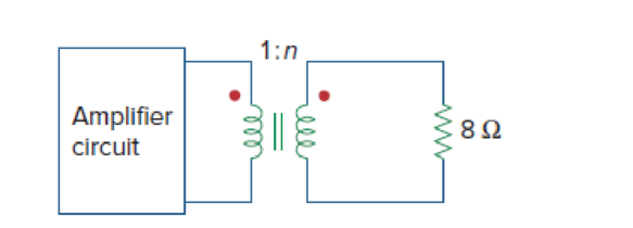
A transformer is used to match an amplifier with an 8-Ω load as shown in Fig. 13.119. The Thevenin equivalent of the amplifier is: VTh = 10 V, ZTh = 128 Ω.
- (a) Find the required turns ratio for maximum energy power transfer.
- (b) Determine the primary and secondary currents.
- (c) Calculate the primary and secondary voltages.
Expert Solution & Answer
Want to see the full answer?
Check out a sample textbook solution
Students have asked these similar questions
For the circuit shown in Figure below find;
a) The value of RL for maximum power transfer.
b) The maximum output power.
(Ans. 9 Ω, 13.44W)
R
R3
3Ω
R4
2Ω a
R2
12 ΩΣ
E
RL
12V
2A
A multipurpose transformer has a secondary coil with several points at which a voltage can be extracted, giving outputs of 5.60, 12.0, and 480 V. (a) The input voltage is 240 V to a primary coil of 280 turns. What are the numbers of turns in the parts of the secondary used to produce the outputvoltages? (b) If the maximum input current is 5.00 A, what arethe maximum output currents (each used alone)?
Design a half-wave AC to DC single-phase converter circuit to produce an average output voltage of 10 V across a 50 Ω resistor from a source of 200 V. Also, determine the power absorbed by the resistor.
Chapter 13 Solutions
Fundamentals of Electric Circuits
Ch. 13.2 - Determine the voltage Vo in the circuit of Fig....Ch. 13.2 - Determine the phasor currents I1 and I2 in the...Ch. 13.3 - Prob. 3PPCh. 13.4 - Find the input impedance of the circuit in Fig....Ch. 13.4 - For the linear transformer in Fig. 13.26(a), find...Ch. 13.4 - Solve the problem in Example 13.1 (see Fig. 13.9)...Ch. 13.5 - The primary current to an ideal transformer rated...Ch. 13.5 - In the ideal transformer circuit of Fig. 13.38,...Ch. 13.5 - Find Vo in the circuit of Fig. 13.40. Figure 13.40...Ch. 13.6 - Refer to Fig. 13.43. If the two-winding...
Ch. 13.6 - In the autotransformer circuit of Fig. 13.45, find...Ch. 13.7 - Prob. 12PPCh. 13.8 - Prob. 13PPCh. 13.9 - Refer to Fig. 13.61. Calculate the turns ratio...Ch. 13.9 - Calculate the turns ratio of an ideal transformer...Ch. 13.9 - In Example 13.17, if the eight 100-W bulbs are...Ch. 13 - Refer to the two magnetically coupled coils of...Ch. 13 - Prob. 2RQCh. 13 - Prob. 3RQCh. 13 - Prob. 4RQCh. 13 - The ideal transformer in Fig. 13.70(a) has N2/N1 =...Ch. 13 - Prob. 6RQCh. 13 - A three-winding transformer is connected as...Ch. 13 - Prob. 8RQCh. 13 - Prob. 9RQCh. 13 - Prob. 10RQCh. 13 - For the three coupled coils in Fig. 13.72,...Ch. 13 - Using Fig. 13.73, design a problem to help other...Ch. 13 - Two coils connected in series-aiding fashion have...Ch. 13 - (a) For the coupled coils in Fig. 13.74(a), show...Ch. 13 - Two coils are mutually coupled, with L1 = 50 mH,...Ch. 13 - Given the circuit shown in Fig. 13.75, determine...Ch. 13 - For the circuit in Fig. 13.76, find Vo. Figure...Ch. 13 - Find v(t) for the circuit in Fig. 13.77.Ch. 13 - Prob. 9PCh. 13 - Find vo in the circuit of Fig. 13.79. Figure 13.79...Ch. 13 - Use mesh analysis to find ix in Fig. 13.80, where...Ch. 13 - Determine the equivalent Leq in the circuit of...Ch. 13 - For the circuit in Fig. 13.82, determine the...Ch. 13 - Obtain the Thevenin equivalent circuit for the...Ch. 13 - Find the Norton equivalent for the circuit in Fig....Ch. 13 - Obtain the Norton equivalent at terminals a-b of...Ch. 13 - In the circuit of Fig. 13.86, ZL is a 15-mH...Ch. 13 - Find the Thevenin equivalent to the left of the...Ch. 13 - Determine an equivalent T-section that can be used...Ch. 13 - Determine currents I1, I2, and I3 in the circuit...Ch. 13 - Prob. 21PCh. 13 - Find current Io in the circuit of Fig. 13.91.Ch. 13 - Let is = 5 cos (100t) A. Calculate the voltage...Ch. 13 - In the circuit of Fig. 13.93, (a) find the...Ch. 13 - Prob. 25PCh. 13 - Find Io in the circuit of Fig. 13.95. Switch the...Ch. 13 - Find the average power delivered to the 50-...Ch. 13 - In the circuit of Fig. 13.97, find the value of X...Ch. 13 - Prob. 29PCh. 13 - (a) Find the input impedance of the circuit in...Ch. 13 - Using Fig. 13.100, design a problem to help other...Ch. 13 - Two linear transformers are cascaded as shown in...Ch. 13 - Determine the input impedance of the air-core...Ch. 13 - Using Fig. 13.103, design a problem to help other...Ch. 13 - Find currents I1, I2, and I3 in the circuit of...Ch. 13 - As done in Fig. 13.33, obtain the relationships...Ch. 13 - A 2402,400-V rms step-up ideal transformer...Ch. 13 - Design a problem to help other students better...Ch. 13 - A 1,200240-V rms transformer has impedance on the...Ch. 13 - The primary of an ideal transformer with a turns...Ch. 13 - Given I2 = 2 A, determine the value of Is in Fig....Ch. 13 - For the circuit in Fig. 13.107, determine the...Ch. 13 - Obtain V1 and V2 in the ideal transformer circuit...Ch. 13 - In the ideal transformer circuit of Fig. 13.109,...Ch. 13 - For the circuit in Fig. 13.110, find the value of...Ch. 13 - (a) Find I1 and I2 in the circuit of Fig. 13.111...Ch. 13 - Prob. 47PCh. 13 - Using Fig. 13.113, design a problem to help other...Ch. 13 - Find current ix in the ideal transformer circuit...Ch. 13 - Prob. 50PCh. 13 - Use the concept of reflected impedance to find the...Ch. 13 - For the circuit in Fig. 13.117, determine the...Ch. 13 - Refer to the network in Fig. 13.118. (a) Find n...Ch. 13 - A transformer is used to match an amplifier with...Ch. 13 - For the circuit in Fig. 13.120, calculate the...Ch. 13 - Find the power absorbed by the 100- resistor in...Ch. 13 - For the ideal transformer circuit of Fig. 13.122...Ch. 13 - Determine the average power absorbed by each...Ch. 13 - In the circuit of Fig. 13.124, let vs = 165...Ch. 13 - Refer to the circuit in Fig. 13.125 on the...Ch. 13 - For the circuit in Fig. 13.126, find Il, I2, and...Ch. 13 - For the network in Fig. 13.127, find: (a) the...Ch. 13 - Find the mesh currents in th circuit of Fig....Ch. 13 - For the circuit in Fig. 13.129. find the turns...Ch. 13 - Calculate the average power dissipated by the 20-...Ch. 13 - Design a problem to help other students better...Ch. 13 - An autotransformer with a 40 percent tap is...Ch. 13 - In the ideal autotransformer of Fig. 13.131,...Ch. 13 - In the circuit of Fig. 13.131, N1 = 190 turns and...Ch. 13 - In the ideal transformer circuit shown in Fig....Ch. 13 - When individuals travel, their electrical...Ch. 13 - In order to meet an emergency, three single-phase...Ch. 13 - Figure 13.135 on the next page shows a three-phase...Ch. 13 - Consider the three-phase transformer shown in Fig....Ch. 13 - A balanced three-phase transformer bank with the...Ch. 13 - Using Fig. 13.138, design a problem to help other...Ch. 13 - The three-phase system of a town distributes power...Ch. 13 - Use PSpice or MultiSim to determine the mesh...Ch. 13 - Use PSpice or MultiSim to find I1, I2, and I3 in...Ch. 13 - Prob. 80PCh. 13 - Use PSpice or MultiSim to find I1, I2, and I3 in...Ch. 13 - A stereo amplifier circuit with ail output...Ch. 13 - A transformer having 2,400 turns on the primary...Ch. 13 - A radio receiver has an input resistance of 300 ....Ch. 13 - A step-down power transformer with a turns ratio...Ch. 13 - A 240120-V rms power transformer is rated at 10...Ch. 13 - A 4-kVA, 2,400240-V rms transformer has 250 turns...Ch. 13 - A 25,000240-V rms distribution transformer has a...Ch. 13 - A 4,800-V rms transmission line feeds a...Ch. 13 - A four-winding transformer (Fig. 13.146) is often...Ch. 13 - A 440/110-V ideal transformer can be connected to...Ch. 13 - Ten bulbs in parallel are supplied by a 7,200120-V...
Knowledge Booster


Learn more about
Need a deep-dive on the concept behind this application? Look no further. Learn more about this topic, electrical-engineering and related others by exploring similar questions and additional content below.Similar questions
- Example: For the circuit shown in Figure below find; a) The value of R1 for maximum power transfer. b) The maximum output power. ( Ans. 9 Ω, 13.44W) R, R3 R4 2Ω a R2 12 Q E R 12V 2A b Solution:arrow_forwardDesign a half- / full-wave AC to DC single-phase converter circuit to produce an average output voltage of 10 V across a 50 Ω resistor from a source of 200 V. Also, determine the power absorbed by the resistor.arrow_forwardQ1: A buck converter is supplied from a 50V battery source. Given: L=400uH, C=100uF, R=20 Ohm, f=20KHZ and D=0.4, Calculate: (a) output voltage (b) maximum and minimum inductor current, (c) output voltage ripple. Q2: A buck converter has an input voltage of 50V and output of 25V. The switching frequency is 10KHZ. The power output is 125W. Determine (a)the duty cycle, (b) the value of L to limit the peak inductor current to 6.25A, (c) the value of capacitance to limit the output voltage ripple factor to 0.5%. Q3: Design a buck converter such that the output voltage is 28V when the input is 48v. The load is 80hm. (a)Design the converter such that it will be in continuous current mode. (b)The capacitance realized output voltage ripple must not be more than 0.5%. (c) The inductance that limits the current ripples within 30% (d) Select the appropriate power switch also. Q4: Design a buck converter such that the output voltage varies between from 20V to 28V while the input voltage is 40V.…arrow_forward
- As shown in the circuit below, a transformer is used to match an amplifier with an 8-ohm load. The Thevenin equivalent of the amplifier is Vth = 10 V, Zth = 128 ohms. What is the required turns ratio n for maximum power transfer? 1:n Amplifier circuit ell 892arrow_forward2. A DC-DC step-up, Boost Converter is shown on Figure 3. Input voltage, Va = 5V, output voltage V, = 12V and R1oad = 142, L = 12µH, C = 200µF, f; = 200kHz. If the losses are negligible, determine the following: a) The switch duty ratio, D. b) Sketch the input current, ia (t). c) Calculate the average value of the input current, Ia. d) Does the converter operate in the continuous or discontinuous conduction mode? Explain! e) Calculate the output voltage ripple. R + V Va Figure 3arrow_forward13.11 Find the value of Rf necessary to produce an output that is five times the sum of the inputs in the circuit below: R; R1 +I Vo W 22 kl 22 k2 R2 +1.8 VoW VOUT 22 klarrow_forward
- A series resonant de-dc converter operates with a dc input voltage of V = 550 V. The converter supplies 30 kV to a load. The de load power varies over the range 5 kW to 25 kW. It is desired to operate the power transistors with zero-voltage switching. The maximum feasible switching frequency is 50 kHz. An isolation transformer having a 1:n turns ratio is connected in series with the tank network. The peak tank capacitor voltage should be no greater than 2000 V, referred to the primary. (a) Derive expressions for the peak tank capacitor voltage and peak tank inductor current. (b) Select values for the tank inductance, tank capacitance, and turns ratio, such that the given spec- ifications are met. Attempt to minimize the peak tank inductor current, while maximizing the worst-case minimum switching frequency.arrow_forward2. Draw a circuit schematic indicating how you will connect your DC power supply to provide +8 V, -8 V and a 0 V common. 3. Draw a circuit schematic (including IC pin numbers and bypass capacitors) for Part A, D, E being sure to note which resistor values you will be using (this may require calculations in advance). 4. Design matrix for digital-to-analog converterarrow_forwardThe transducer, which have the negative temperature coefficient characteristics is, O Thermocouples O RTD O Thermistor O LVDT When a transformer takes a current of 0.5 A and its primary is connected to a 235 V, 50 Hz supply, the secondary being open circuited. If the power absorbed is 84 W, then the iron loss current isarrow_forward
- A solar energy installation utilize a three phase bridge converter to feed energy into power system through a transformer of 400 V/400 V, as shown below. The energy is collected in a bank of 400 V battery and is connected to converter through a large filter choke of resistance 10 N. Q. The kVA rating of the input transformer is # 38 H* Filter choke Batteryarrow_forwardA buck converter is designed to supply a 5V cell phone from a 12V car battery. Determine the duty ratioarrow_forwardQuestion 3) A figure below shows a power electronics converter system that are used to obtain a DC 600V at the load terminal from an AC utility, DC link Converter I 220V, 50HZ 500μΕ Converter II 600 DC Full-bridge Fixed AC 1000 DC Voltage Duty cycle (D) a) Named the required converters I and II b) Draw the circuit diagram of each converter c) Compute the input voltage of converter II d) Design the required duty cycle of converter II to obtain 600VDC at the output. e) Determine the DC output current of converter I.arrow_forward
arrow_back_ios
SEE MORE QUESTIONS
arrow_forward_ios
Recommended textbooks for you
 Introductory Circuit Analysis (13th Edition)Electrical EngineeringISBN:9780133923605Author:Robert L. BoylestadPublisher:PEARSON
 Delmar's Standard Textbook Of ElectricityElectrical EngineeringISBN:9781337900348Author:Stephen L. HermanPublisher:Cengage Learning
 Programmable Logic ControllersElectrical EngineeringISBN:9780073373843Author:Frank D. PetruzellaPublisher:McGraw-Hill Education
 Fundamentals of Electric CircuitsElectrical EngineeringISBN:9780078028229Author:Charles K Alexander, Matthew SadikuPublisher:McGraw-Hill Education
 Electric Circuits. (11th Edition)Electrical EngineeringISBN:9780134746968Author:James W. Nilsson, Susan RiedelPublisher:PEARSON
 Engineering ElectromagneticsElectrical EngineeringISBN:9780078028151Author:Hayt, William H. (william Hart), Jr, BUCK, John A.Publisher:Mcgraw-hill Education,
Introductory Circuit Analysis (13th Edition)
Electrical Engineering
ISBN:9780133923605
Author:Robert L. Boylestad
Publisher:PEARSON
Delmar's Standard Textbook Of Electricity
Electrical Engineering
ISBN:9781337900348
Author:Stephen L. Herman
Publisher:Cengage Learning
Programmable Logic Controllers
Electrical Engineering
ISBN:9780073373843
Author:Frank D. Petruzella
Publisher:McGraw-Hill Education
Fundamentals of Electric Circuits
Electrical Engineering
ISBN:9780078028229
Author:Charles K Alexander, Matthew Sadiku
Publisher:McGraw-Hill Education
Electric Circuits. (11th Edition)
Electrical Engineering
ISBN:9780134746968
Author:James W. Nilsson, Susan Riedel
Publisher:PEARSON
Engineering Electromagnetics
Electrical Engineering
ISBN:9780078028151
Author:Hayt, William H. (william Hart), Jr, BUCK, John A.
Publisher:Mcgraw-hill Education,
TRANSFORMERS - What They Are, How They Work, How Electricians Size Them; Author: Electrician U;https://www.youtube.com/watch?v=tXPy4OE7ApE;License: Standard Youtube License