
Concept explainers
Videos
Find the Thevenin equivalent to the left of the load Z in the circuit of Fig. 13.87.
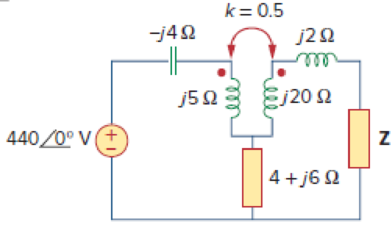
Calculate the Thevenin equivalent to the left side of load Z in the coupled coils circuit.
Answer to Problem 18P
The Thevenin equivalent circuit parameters are
Explanation of Solution
Given data:
Refer to Figure 13.87 in the textbook for the circuit with coupled coils.
Calculation:
To the Thevenin’s voltage, open-circuit the impedance Z. Then, the current
Modify the Figure 13.87 by convert the circuit into the frequency domain and convert the coupled inductors into their dependent source equivalent. The modified circuit as shown in Figure 1.

Apply Kirchhoff's voltage law to the loop 1 contains current
Substitute 0 for
Modify the Equation as follows.
Write the expression for the open-circuit voltage.
Substitute
Consider the expression for the Thevenin voltage.
Substitute
Modify the Figure 1 by short-circuiting the load side contains current
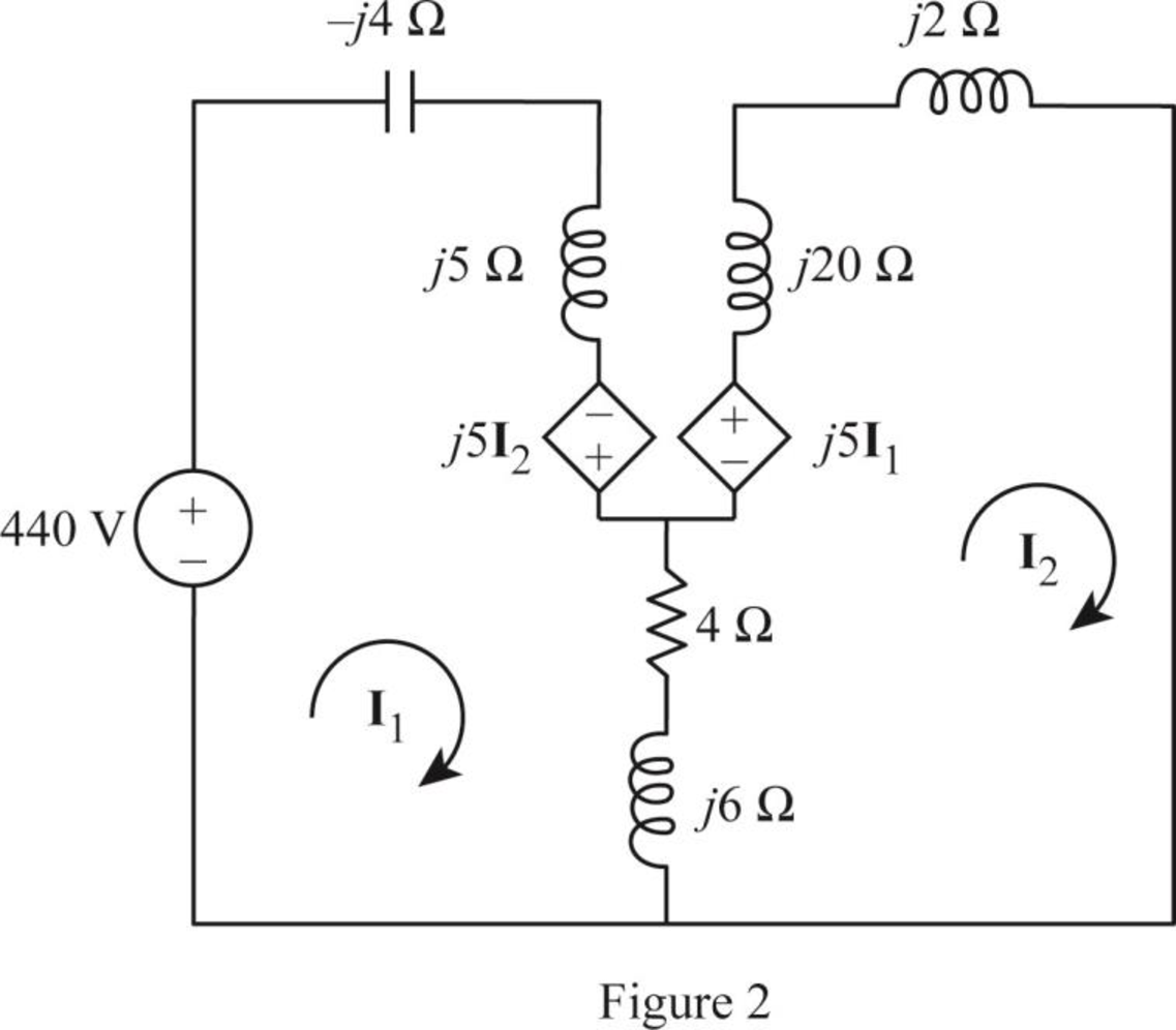
From Figure 2, consider that the loops 1 and 2 contain the currents
Apply Kirchhoff's voltage law to the loop 1 in Figure 1.
Apply Kirchhoff's voltage law to the loop 2 in Figure 1.
Write equations (1) and (2) in matrix form as follows.
Write the MATLAB code to solve the equation (3).
A = [(4+j*7) -(4+j*11);-(4+j*11) (4+j*28)];
B = [440; 0];
I = inv(A)*B
The output in command window:
I =
61.069 - 121.926i
14.369 - 54.571i
From the MATLAB output, the currents
And
The short-circuit current
Substitute
Write the expression for Thevenin’s equivalent impedance.
Substitute
Conclusion:
Thus, the Thevenin equivalent circuit parameters are
Want to see more full solutions like this?
Chapter 13 Solutions
Fundamentals of Electric Circuits


- The diagram shown below is a typical tuning circuit. Considering this circuit comprises a transformer (with a coil ratio of 20:1 and an HV side voltage of 240V ), a capacitor of impedance -j20Ω, an inductor of impedance j40Ω, and a 50Ω resistor, determine: the current supplied by the source the impedance seen at the supply (HV side) the power dissipated by the resistor the operating power factor of the fitting If the capacitor is now removed from the above circuit and is placed in parallel with the secondary of the transformer, redraw the circuit diagram and recalculate parts a. to d. in question (i). Draw the phasor diagram for both series and parallel RLC circuits in parts (i) and (ii). Discuss the effects of changing the capacitor connection in parallel on the power factor of the circuit. State the benefits of using the transformer in the above circuit. Explain the operating principle of the transformer with particular reference to electro-magnetic…arrow_forwardVariation of which of the following parameter is not consider as power quality problem for industry?VoltageCurrentPowerFrequencyarrow_forward5. Magnetically-Coupled circuitarrow_forward
- Calculate the mesh currents in the circuit of Fig. 13.11.arrow_forwardHW19 *13.22 Find current I, in the circuit of Fig. 13.91. -j 50 2 I. j20 Ω j40 2 j60 2. j102 j80 23 j30 2 50/0° V 100 2 wwarrow_forwardIn the ideal transformer circuit of Fig. 13.38, find and the complexpower supplied by the source.arrow_forward
- Fundamentals of Electrical Engineering 2020/2021 na ea Dr. Yaseen H. Tahir Example: Find the voltage Vo in the circuit in Figure belownin 2 kn 3 kN 41, Vs 10 mA 4 k2 Solution: wongs.senlo vleoleyy son bas s) 2 llaw es (s be ) amioq soni2 Jutoeu o ei noitsion A vlgne Jaum ow aglowondnu or gniniomotob of obno nl getlov oln adi to teianoo isdi disq boeolo oniolab otanolenadT e ul deq sdl ou n ov ( anielsb o ba 1 b we 62 g s 1o darrow_forward5.1arrow_forwarda device has an average power rating of 1200W and deisgn to operate 250V rms line. detrmine the effective resistance if the power socket available has 115V rms line and uses a step up ideal transformer from 115V to 250V.arrow_forward
 Introductory Circuit Analysis (13th Edition)Electrical EngineeringISBN:9780133923605Author:Robert L. BoylestadPublisher:PEARSON
 Delmar's Standard Textbook Of ElectricityElectrical EngineeringISBN:9781337900348Author:Stephen L. HermanPublisher:Cengage Learning
 Programmable Logic ControllersElectrical EngineeringISBN:9780073373843Author:Frank D. PetruzellaPublisher:McGraw-Hill Education
 Fundamentals of Electric CircuitsElectrical EngineeringISBN:9780078028229Author:Charles K Alexander, Matthew SadikuPublisher:McGraw-Hill Education
 Electric Circuits. (11th Edition)Electrical EngineeringISBN:9780134746968Author:James W. Nilsson, Susan RiedelPublisher:PEARSON
 Engineering ElectromagneticsElectrical EngineeringISBN:9780078028151Author:Hayt, William H. (william Hart), Jr, BUCK, John A.Publisher:Mcgraw-hill Education,