
Fundamentals of Electric Circuits
6th Edition
ISBN: 9780078028229
Author: Charles K Alexander, Matthew Sadiku
Publisher: McGraw-Hill Education
expand_more
expand_more
format_list_bulleted
Concept explainers
Videos
Textbook Question
Chapter 13, Problem 5RQ
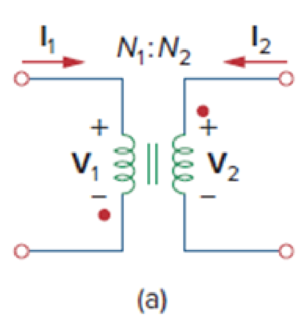
The ideal transformer in Fig. 13.70(a) has N2/N1 = 10. The ratio V2/V1 is:
- (a) 10
- (b) 0.1
- (c) −0.1
- (d) −10
Expert Solution & Answer
Want to see the full answer?
Check out a sample textbook solution
Students have asked these similar questions
Ge
10:1
m
Thanks
Any help will be appreciated.
S
BL
• I am doing a AC DC 12 W Regulated power supply with 110 vrms and 60HZ
as an input, and I need an output of 6v and 9 V. I have the designed
already: the step-down transformer, Resistor as a current limiter to protect
the Zener diode, a capacitor for the ripple voltage, and a 2 state switch (
when the switch is closed to the RL will give 9 V and when is closed to the S
will give 6V as an output).
• I need some support with some calculations to find PIV for each diode //
Average Power// some calculations in how to find the values for the
resistors and capacitors to accomplish the desire output // and some
calculations for the ripple voltage. Note: the Zener is regulated to 9v.
I know the RL>R to get the desire output.
In the given circuit, a step down transformer
with an RMS voltage as 220V | 22 V is used
with RL = 3 KN.
Assume diode as Silicon and the input
frequency is F= 70 Hz.
A
D3
D1
AC in
D2
D4
LOAD
B
1- Name the given circuit .
2- Find The PIV.
3- Find Current trough load resistance.
4- Draw the Input and Output wave forms.
You are given five light bulbs designed to operate on 160 mA current at 3.0 V (rms values), arid want to connect them in parallel, through an ideal transformer, to 120 V rms AC household power. a) Draw a circuit diagram showing the AC power source (a generator symbol ), the transformer, and resistors for the light bulbs. b) Is the required transformer step-up or step-down? What turns ratio N5/N is needed? e) Calculate the ruts current through both the primary and secondary coils of the trans former, in mA.
Chapter 13 Solutions
Fundamentals of Electric Circuits
Ch. 13.2 - Determine the voltage Vo in the circuit of Fig....Ch. 13.2 - Determine the phasor currents I1 and I2 in the...Ch. 13.3 - Prob. 3PPCh. 13.4 - Find the input impedance of the circuit in Fig....Ch. 13.4 - For the linear transformer in Fig. 13.26(a), find...Ch. 13.4 - Solve the problem in Example 13.1 (see Fig. 13.9)...Ch. 13.5 - The primary current to an ideal transformer rated...Ch. 13.5 - In the ideal transformer circuit of Fig. 13.38,...Ch. 13.5 - Find Vo in the circuit of Fig. 13.40. Figure 13.40...Ch. 13.6 - Refer to Fig. 13.43. If the two-winding...
Ch. 13.6 - In the autotransformer circuit of Fig. 13.45, find...Ch. 13.7 - Prob. 12PPCh. 13.8 - Prob. 13PPCh. 13.9 - Refer to Fig. 13.61. Calculate the turns ratio...Ch. 13.9 - Calculate the turns ratio of an ideal transformer...Ch. 13.9 - In Example 13.17, if the eight 100-W bulbs are...Ch. 13 - Refer to the two magnetically coupled coils of...Ch. 13 - Prob. 2RQCh. 13 - Prob. 3RQCh. 13 - Prob. 4RQCh. 13 - The ideal transformer in Fig. 13.70(a) has N2/N1 =...Ch. 13 - Prob. 6RQCh. 13 - A three-winding transformer is connected as...Ch. 13 - Prob. 8RQCh. 13 - Prob. 9RQCh. 13 - Prob. 10RQCh. 13 - For the three coupled coils in Fig. 13.72,...Ch. 13 - Using Fig. 13.73, design a problem to help other...Ch. 13 - Two coils connected in series-aiding fashion have...Ch. 13 - (a) For the coupled coils in Fig. 13.74(a), show...Ch. 13 - Two coils are mutually coupled, with L1 = 50 mH,...Ch. 13 - Given the circuit shown in Fig. 13.75, determine...Ch. 13 - For the circuit in Fig. 13.76, find Vo. Figure...Ch. 13 - Find v(t) for the circuit in Fig. 13.77.Ch. 13 - Prob. 9PCh. 13 - Find vo in the circuit of Fig. 13.79. Figure 13.79...Ch. 13 - Use mesh analysis to find ix in Fig. 13.80, where...Ch. 13 - Determine the equivalent Leq in the circuit of...Ch. 13 - For the circuit in Fig. 13.82, determine the...Ch. 13 - Obtain the Thevenin equivalent circuit for the...Ch. 13 - Find the Norton equivalent for the circuit in Fig....Ch. 13 - Obtain the Norton equivalent at terminals a-b of...Ch. 13 - In the circuit of Fig. 13.86, ZL is a 15-mH...Ch. 13 - Find the Thevenin equivalent to the left of the...Ch. 13 - Determine an equivalent T-section that can be used...Ch. 13 - Determine currents I1, I2, and I3 in the circuit...Ch. 13 - Prob. 21PCh. 13 - Find current Io in the circuit of Fig. 13.91.Ch. 13 - Let is = 5 cos (100t) A. Calculate the voltage...Ch. 13 - In the circuit of Fig. 13.93, (a) find the...Ch. 13 - Prob. 25PCh. 13 - Find Io in the circuit of Fig. 13.95. Switch the...Ch. 13 - Find the average power delivered to the 50-...Ch. 13 - In the circuit of Fig. 13.97, find the value of X...Ch. 13 - Prob. 29PCh. 13 - (a) Find the input impedance of the circuit in...Ch. 13 - Using Fig. 13.100, design a problem to help other...Ch. 13 - Two linear transformers are cascaded as shown in...Ch. 13 - Determine the input impedance of the air-core...Ch. 13 - Using Fig. 13.103, design a problem to help other...Ch. 13 - Find currents I1, I2, and I3 in the circuit of...Ch. 13 - As done in Fig. 13.33, obtain the relationships...Ch. 13 - A 2402,400-V rms step-up ideal transformer...Ch. 13 - Design a problem to help other students better...Ch. 13 - A 1,200240-V rms transformer has impedance on the...Ch. 13 - The primary of an ideal transformer with a turns...Ch. 13 - Given I2 = 2 A, determine the value of Is in Fig....Ch. 13 - For the circuit in Fig. 13.107, determine the...Ch. 13 - Obtain V1 and V2 in the ideal transformer circuit...Ch. 13 - In the ideal transformer circuit of Fig. 13.109,...Ch. 13 - For the circuit in Fig. 13.110, find the value of...Ch. 13 - (a) Find I1 and I2 in the circuit of Fig. 13.111...Ch. 13 - Prob. 47PCh. 13 - Using Fig. 13.113, design a problem to help other...Ch. 13 - Find current ix in the ideal transformer circuit...Ch. 13 - Prob. 50PCh. 13 - Use the concept of reflected impedance to find the...Ch. 13 - For the circuit in Fig. 13.117, determine the...Ch. 13 - Refer to the network in Fig. 13.118. (a) Find n...Ch. 13 - A transformer is used to match an amplifier with...Ch. 13 - For the circuit in Fig. 13.120, calculate the...Ch. 13 - Find the power absorbed by the 100- resistor in...Ch. 13 - For the ideal transformer circuit of Fig. 13.122...Ch. 13 - Determine the average power absorbed by each...Ch. 13 - In the circuit of Fig. 13.124, let vs = 165...Ch. 13 - Refer to the circuit in Fig. 13.125 on the...Ch. 13 - For the circuit in Fig. 13.126, find Il, I2, and...Ch. 13 - For the network in Fig. 13.127, find: (a) the...Ch. 13 - Find the mesh currents in th circuit of Fig....Ch. 13 - For the circuit in Fig. 13.129. find the turns...Ch. 13 - Calculate the average power dissipated by the 20-...Ch. 13 - Design a problem to help other students better...Ch. 13 - An autotransformer with a 40 percent tap is...Ch. 13 - In the ideal autotransformer of Fig. 13.131,...Ch. 13 - In the circuit of Fig. 13.131, N1 = 190 turns and...Ch. 13 - In the ideal transformer circuit shown in Fig....Ch. 13 - When individuals travel, their electrical...Ch. 13 - In order to meet an emergency, three single-phase...Ch. 13 - Figure 13.135 on the next page shows a three-phase...Ch. 13 - Consider the three-phase transformer shown in Fig....Ch. 13 - A balanced three-phase transformer bank with the...Ch. 13 - Using Fig. 13.138, design a problem to help other...Ch. 13 - The three-phase system of a town distributes power...Ch. 13 - Use PSpice or MultiSim to determine the mesh...Ch. 13 - Use PSpice or MultiSim to find I1, I2, and I3 in...Ch. 13 - Prob. 80PCh. 13 - Use PSpice or MultiSim to find I1, I2, and I3 in...Ch. 13 - A stereo amplifier circuit with ail output...Ch. 13 - A transformer having 2,400 turns on the primary...Ch. 13 - A radio receiver has an input resistance of 300 ....Ch. 13 - A step-down power transformer with a turns ratio...Ch. 13 - A 240120-V rms power transformer is rated at 10...Ch. 13 - A 4-kVA, 2,400240-V rms transformer has 250 turns...Ch. 13 - A 25,000240-V rms distribution transformer has a...Ch. 13 - A 4,800-V rms transmission line feeds a...Ch. 13 - A four-winding transformer (Fig. 13.146) is often...Ch. 13 - A 440/110-V ideal transformer can be connected to...Ch. 13 - Ten bulbs in parallel are supplied by a 7,200120-V...
Knowledge Booster


Learn more about
Need a deep-dive on the concept behind this application? Look no further. Learn more about this topic, electrical-engineering and related others by exploring similar questions and additional content below.Similar questions
- If the input voltage for the given circuit below is 220 V at 60 Hz, the load resistance (RL) is 3302 and the average output voltage is 20 V. Assume the diodes to be silicon diodes. Determine the turns ratio of the transformer used. If a capacitor of 100 µF is connected parallel to the load resistor (RL), Determine the ripple factor. D3 D1 V + RL D2 D4 a. The turns ratio of transformer (Npri/Nsec) is b. The Ripple factor is illlarrow_forwardQ3: A three stage Cockroft-Walton generator is supplied by 212.133 V, 50 Hz source via a transformer with turns ratio equals to 2/800. All capacitors have a value of (0.8 µF). The protection current equals to 15 mA. Find the following: a. Find the output peak voltage that is used for testing without considering the voltage drop. b. Find the output peak voltage that is used for testing with considering the voltage drop. c. What is the ripple voltage? d. If the lowest capacitor is increased to twice its value, what is the output peak voltage that is used for testing with considering the voltage drop. e. Comparing the results of ( b ) and ( d ) above , do you recommend doubling the value of the lowest capacitor or not? f. According to the circuit values, is the 3 stages represents the optimum number of stages for this generator?arrow_forwardIf the input voltage for the given circuit below is 220 V at 50 Hz, the load resistance (RL) is 3300 and the average output voltage is 20 V. Assume the diodes to be germanium diodes. Determine the turns ratio of the transformer used. If a capacitor of 100 µF is connected parallel to the load resistor (RL), Determine the ripple factor. D1 D2 V D3 .... D4 RL a. The turns ratio of transformer (Npri/Nsec) is b. The Ripple factor is cell rellarrow_forward
- If the input voltage for the given circuit below is 220 V at 50 Hz, the load resistance (RL) is 4700 and the average output voltage is 25 V. Assume the diodes to be silicon diodes. Determine the turns ratio of the transformer used. If a capacitor of 120 µF is connected parallel to the load resistor (RL), Determine the ripple factor. D3 D1 V D2 a. The turns ratio of transformer (Npri/Nsec) is b. The Ripple factor is llle ellarrow_forward1- In a buck DC/DC converter: ton V₁ = 100 V, R= 80, D ==0.8, f == 20000 Hz, L = 200 μH, Find: a) average voltage and current of the load Vala. b) maximum and minimum current of inductor. c) Voltage ripple of the capacitor. d) the average input current. e) draw the figure of the inductor current. C1 = 40 Micro farad Q Vd - İd K C1 ww + Voarrow_forward1. A coil has a resistance of 18 ohm when its mean temperature is 20 °C and of 20 ohm when its mean temperature is 50°C . Find the mean temperature rise when its resistance is 21 ohm and the surroundings isn15 °C.arrow_forward
- FACTS: AC-DC converters take the AC power from wall outlets and convert it to unregulated DC. These power supplies include transformers that change the voltage of the AC that comes through wall outlets, rectifiers to save it from AC to DC and a filter that removes noise from the peaks and troths of the AC power waves.The DC-to-AC Converters are used to charge the batteries in the vehicles. These circuits are mainly used for driving low-power AC motors and are used in a solar power system. The DC to AC converters can be used in dc transmission lines for transmitting power to loads. QUESTION: What do you think is the main reason why we have AC power in our outlets instead of DC power? Explain your answer.arrow_forwardQ2. Correct the wrong sentence if you find it in only (all) of the following sentences: 8) The primary mmf is not equal and same direction to the secondary mmf in an ideal transformer. 9) The open circuit test is conducted at the rated current and the short-circuit test performed at the rated voltage. 10) The short-circuit test is performed on low voltage side and The open circuit test is on the high-voltage side. 11) The copper loss is not affected by the load and the core loss varies with the load. 12) Shunt field winding have a large number of turns compared with a series field winding. 13) The voltage regulation of generator A is 10% and that of generator B is 5%. The generator A is better than generator B. 14) The external characteristic of a dc generator is affected by armature reaction. 15) The commutating poles or interpoles is connected in parallel with the armature. 16) The dc motor should be started by impressing its rated voltage across the armature terminals. 17) The…arrow_forwardA single phase bridge rectifier supplied from a 120V - 50 Hz sinusoidal source is connected to an inductive load. The general expression of the RMS AC component of the current is given below where Vm is the maximum input voltage. If R = 500 Q and L = 1H, then the current ripple factor RF, would be equal to: 4Vm IAc = V2. r. R2 + (2wL)² Select one: O a. 1 O b. 0.8 O C. 0.5 O d. 0.29 TOSHIBAarrow_forward
- Q2: A 100-ohm resistor is connected to the secondary of an ideal transformer with a turns ratio of 1:4 (primary to secondary). A 10-V rms, 1-kHz voltage source is connected to the primary. Calculate the primary current and the voltage across the 100 - ohm resistor.arrow_forward11. Two coupled coils have self-inductances L1 = 2 H and L2 = 0.5 H, and a coefficient of coupling K = 0.9. Determine the turns ratio N1/N2 of the two coils. a. 2 b. 0.2 c. 0.5 d. 0.9arrow_forwardSome electronic devices operate on a DC voltage of 7.5 V. To obtain 7.5 V DC from a 120-V (rms) AC line, first the voltage is dropped to 7.5 V (rms) AC by a transformer, and then the 7.5 V AC is converted to 7.5 V DC by a rectifier circuit involving diodes. Consider a device of resistance 15 Ω connected to the 7.5-V DC output of the rectifier. Again assuming no power loss anywhere, what is the rms current, in milliamperes, in the primary winding?arrow_forward
arrow_back_ios
SEE MORE QUESTIONS
arrow_forward_ios
Recommended textbooks for you
 Introductory Circuit Analysis (13th Edition)Electrical EngineeringISBN:9780133923605Author:Robert L. BoylestadPublisher:PEARSON
 Delmar's Standard Textbook Of ElectricityElectrical EngineeringISBN:9781337900348Author:Stephen L. HermanPublisher:Cengage Learning
 Programmable Logic ControllersElectrical EngineeringISBN:9780073373843Author:Frank D. PetruzellaPublisher:McGraw-Hill Education
 Fundamentals of Electric CircuitsElectrical EngineeringISBN:9780078028229Author:Charles K Alexander, Matthew SadikuPublisher:McGraw-Hill Education
 Electric Circuits. (11th Edition)Electrical EngineeringISBN:9780134746968Author:James W. Nilsson, Susan RiedelPublisher:PEARSON
 Engineering ElectromagneticsElectrical EngineeringISBN:9780078028151Author:Hayt, William H. (william Hart), Jr, BUCK, John A.Publisher:Mcgraw-hill Education,
Introductory Circuit Analysis (13th Edition)
Electrical Engineering
ISBN:9780133923605
Author:Robert L. Boylestad
Publisher:PEARSON
Delmar's Standard Textbook Of Electricity
Electrical Engineering
ISBN:9781337900348
Author:Stephen L. Herman
Publisher:Cengage Learning
Programmable Logic Controllers
Electrical Engineering
ISBN:9780073373843
Author:Frank D. Petruzella
Publisher:McGraw-Hill Education
Fundamentals of Electric Circuits
Electrical Engineering
ISBN:9780078028229
Author:Charles K Alexander, Matthew Sadiku
Publisher:McGraw-Hill Education
Electric Circuits. (11th Edition)
Electrical Engineering
ISBN:9780134746968
Author:James W. Nilsson, Susan Riedel
Publisher:PEARSON
Engineering Electromagnetics
Electrical Engineering
ISBN:9780078028151
Author:Hayt, William H. (william Hart), Jr, BUCK, John A.
Publisher:Mcgraw-hill Education,
Current Divider Rule; Author: Neso Academy;https://www.youtube.com/watch?v=hRU1mKWUehY;License: Standard YouTube License, CC-BY