
Fundamentals of Electric Circuits
6th Edition
ISBN: 9780078028229
Author: Charles K Alexander, Matthew Sadiku
Publisher: McGraw-Hill Education
expand_more
expand_more
format_list_bulleted
Concept explainers
Videos
Textbook Question
Chapter 13, Problem 74P
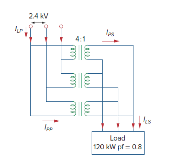
Consider the three-phase transformer shown in Fig. 13.136. The primary is fed by a three-phase source with line voltage of 2.4 kV rms, while the secondary supplies a three-phase 120-kW balanced load at pf of 0.8. Determine:
- (a) the type of transformer connections,
- (b) the values of ILS and IPS,
- (c) the values of ILP and IPP,
- (d) the kVA rating of each phase of the transformer.
Expert Solution & Answer
Want to see the full answer?
Check out a sample textbook solution
Students have asked these similar questions
Consider the following circuit, assuming the switch has been in the same position for a long period of time before t = 0:
Vx
L
iL
R3
R2
R₁
Is
+
Vo
-
コロ
>Where Is = 100 mA,R=2202, R2 = 4702,R3 =4702,L= 1 mH. As indicated on the diagram, before t = 0, the switch is closed, after t = 0 the switch is open.
1. What are Ve and Vo before the switch shown opens (answer to within 1% accuracy)?
Vx =
V, Vo =
V
2. What is the T of the RL circuit after the switch operates (answer to within 1% accuracy)?
T=
μs
3. Complete the derivation for the inductor current in (t) differential equation below by filling in the blank coefficients (answer to within 1% accuracy):
diy(1)
dt
di (0) +
iz (t)+
= 0
4. Hence or otherwise, find the time domain expression for Vo(t) (answer to within 1% accuracy):
Vo(t)=
exp(
確定圖5-38中的I1、I2和IB。 Vcc=-12 V;R1=33 kN;RC=1.8 kN;βDC = 150;RE=560;R2=5.6 kN 圖 5-38
Consider the following circuit:
Vs
R₁
Vx
ww
C'₁
R2
Where Vs = 3.3 cos(2000t-10) VR:=2202 R2 = 1002,L=1mH, Ci = 22 nF, C2 = 47 nF
N.B. We have been using cosine as the basis for our phasors.
1. What is the impedance of each of R, Ci, L (answer to within 1%):
Z RI =
+j
Q Zci=
+j
QZL=
+jQ
心
2. Complete the following KCL for node Vo, assuming current flowing out of the node is positive (answer to within 1%):
0=
+j
)+Vo/
+j0)+Vo/(0+j
回回回
3. Hence or otherwise solve for Vo in phasor form (answer to within 1% amplitude and 5 degrees of phase):
Vo =
° V
回
4. Convert this phasor to a time domain expression for Vo(t) (answer to within 1% amplitude and 5 degrees of phase):
Vo(t) =
cos(
t+
Vo
1
Chapter 13 Solutions
Fundamentals of Electric Circuits
Ch. 13.2 - Determine the voltage Vo in the circuit of Fig....Ch. 13.2 - Determine the phasor currents I1 and I2 in the...Ch. 13.3 - Prob. 3PPCh. 13.4 - Find the input impedance of the circuit in Fig....Ch. 13.4 - For the linear transformer in Fig. 13.26(a), find...Ch. 13.4 - Solve the problem in Example 13.1 (see Fig. 13.9)...Ch. 13.5 - The primary current to an ideal transformer rated...Ch. 13.5 - In the ideal transformer circuit of Fig. 13.38,...Ch. 13.5 - Find Vo in the circuit of Fig. 13.40. Figure 13.40...Ch. 13.6 - Refer to Fig. 13.43. If the two-winding...
Ch. 13.6 - In the autotransformer circuit of Fig. 13.45, find...Ch. 13.7 - Prob. 12PPCh. 13.8 - Prob. 13PPCh. 13.9 - Refer to Fig. 13.61. Calculate the turns ratio...Ch. 13.9 - Calculate the turns ratio of an ideal transformer...Ch. 13.9 - In Example 13.17, if the eight 100-W bulbs are...Ch. 13 - Refer to the two magnetically coupled coils of...Ch. 13 - Prob. 2RQCh. 13 - Prob. 3RQCh. 13 - Prob. 4RQCh. 13 - The ideal transformer in Fig. 13.70(a) has N2/N1 =...Ch. 13 - Prob. 6RQCh. 13 - A three-winding transformer is connected as...Ch. 13 - Prob. 8RQCh. 13 - Prob. 9RQCh. 13 - Prob. 10RQCh. 13 - For the three coupled coils in Fig. 13.72,...Ch. 13 - Using Fig. 13.73, design a problem to help other...Ch. 13 - Two coils connected in series-aiding fashion have...Ch. 13 - (a) For the coupled coils in Fig. 13.74(a), show...Ch. 13 - Two coils are mutually coupled, with L1 = 50 mH,...Ch. 13 - Given the circuit shown in Fig. 13.75, determine...Ch. 13 - For the circuit in Fig. 13.76, find Vo. Figure...Ch. 13 - Find v(t) for the circuit in Fig. 13.77.Ch. 13 - Prob. 9PCh. 13 - Find vo in the circuit of Fig. 13.79. Figure 13.79...Ch. 13 - Use mesh analysis to find ix in Fig. 13.80, where...Ch. 13 - Determine the equivalent Leq in the circuit of...Ch. 13 - For the circuit in Fig. 13.82, determine the...Ch. 13 - Obtain the Thevenin equivalent circuit for the...Ch. 13 - Find the Norton equivalent for the circuit in Fig....Ch. 13 - Obtain the Norton equivalent at terminals a-b of...Ch. 13 - In the circuit of Fig. 13.86, ZL is a 15-mH...Ch. 13 - Find the Thevenin equivalent to the left of the...Ch. 13 - Determine an equivalent T-section that can be used...Ch. 13 - Determine currents I1, I2, and I3 in the circuit...Ch. 13 - Prob. 21PCh. 13 - Find current Io in the circuit of Fig. 13.91.Ch. 13 - Let is = 5 cos (100t) A. Calculate the voltage...Ch. 13 - In the circuit of Fig. 13.93, (a) find the...Ch. 13 - Prob. 25PCh. 13 - Find Io in the circuit of Fig. 13.95. Switch the...Ch. 13 - Find the average power delivered to the 50-...Ch. 13 - In the circuit of Fig. 13.97, find the value of X...Ch. 13 - Prob. 29PCh. 13 - (a) Find the input impedance of the circuit in...Ch. 13 - Using Fig. 13.100, design a problem to help other...Ch. 13 - Two linear transformers are cascaded as shown in...Ch. 13 - Determine the input impedance of the air-core...Ch. 13 - Using Fig. 13.103, design a problem to help other...Ch. 13 - Find currents I1, I2, and I3 in the circuit of...Ch. 13 - As done in Fig. 13.33, obtain the relationships...Ch. 13 - A 2402,400-V rms step-up ideal transformer...Ch. 13 - Design a problem to help other students better...Ch. 13 - A 1,200240-V rms transformer has impedance on the...Ch. 13 - The primary of an ideal transformer with a turns...Ch. 13 - Given I2 = 2 A, determine the value of Is in Fig....Ch. 13 - For the circuit in Fig. 13.107, determine the...Ch. 13 - Obtain V1 and V2 in the ideal transformer circuit...Ch. 13 - In the ideal transformer circuit of Fig. 13.109,...Ch. 13 - For the circuit in Fig. 13.110, find the value of...Ch. 13 - (a) Find I1 and I2 in the circuit of Fig. 13.111...Ch. 13 - Prob. 47PCh. 13 - Using Fig. 13.113, design a problem to help other...Ch. 13 - Find current ix in the ideal transformer circuit...Ch. 13 - Prob. 50PCh. 13 - Use the concept of reflected impedance to find the...Ch. 13 - For the circuit in Fig. 13.117, determine the...Ch. 13 - Refer to the network in Fig. 13.118. (a) Find n...Ch. 13 - A transformer is used to match an amplifier with...Ch. 13 - For the circuit in Fig. 13.120, calculate the...Ch. 13 - Find the power absorbed by the 100- resistor in...Ch. 13 - For the ideal transformer circuit of Fig. 13.122...Ch. 13 - Determine the average power absorbed by each...Ch. 13 - In the circuit of Fig. 13.124, let vs = 165...Ch. 13 - Refer to the circuit in Fig. 13.125 on the...Ch. 13 - For the circuit in Fig. 13.126, find Il, I2, and...Ch. 13 - For the network in Fig. 13.127, find: (a) the...Ch. 13 - Find the mesh currents in th circuit of Fig....Ch. 13 - For the circuit in Fig. 13.129. find the turns...Ch. 13 - Calculate the average power dissipated by the 20-...Ch. 13 - Design a problem to help other students better...Ch. 13 - An autotransformer with a 40 percent tap is...Ch. 13 - In the ideal autotransformer of Fig. 13.131,...Ch. 13 - In the circuit of Fig. 13.131, N1 = 190 turns and...Ch. 13 - In the ideal transformer circuit shown in Fig....Ch. 13 - When individuals travel, their electrical...Ch. 13 - In order to meet an emergency, three single-phase...Ch. 13 - Figure 13.135 on the next page shows a three-phase...Ch. 13 - Consider the three-phase transformer shown in Fig....Ch. 13 - A balanced three-phase transformer bank with the...Ch. 13 - Using Fig. 13.138, design a problem to help other...Ch. 13 - The three-phase system of a town distributes power...Ch. 13 - Use PSpice or MultiSim to determine the mesh...Ch. 13 - Use PSpice or MultiSim to find I1, I2, and I3 in...Ch. 13 - Prob. 80PCh. 13 - Use PSpice or MultiSim to find I1, I2, and I3 in...Ch. 13 - A stereo amplifier circuit with ail output...Ch. 13 - A transformer having 2,400 turns on the primary...Ch. 13 - A radio receiver has an input resistance of 300 ....Ch. 13 - A step-down power transformer with a turns ratio...Ch. 13 - A 240120-V rms power transformer is rated at 10...Ch. 13 - A 4-kVA, 2,400240-V rms transformer has 250 turns...Ch. 13 - A 25,000240-V rms distribution transformer has a...Ch. 13 - A 4,800-V rms transmission line feeds a...Ch. 13 - A four-winding transformer (Fig. 13.146) is often...Ch. 13 - A 440/110-V ideal transformer can be connected to...Ch. 13 - Ten bulbs in parallel are supplied by a 7,200120-V...
Knowledge Booster


Learn more about
Need a deep-dive on the concept behind this application? Look no further. Learn more about this topic, electrical-engineering and related others by exploring similar questions and additional content below.Similar questions
- is pf leading, lagging or neither?arrow_forward*please use pen and paper to show work (thank you!!!)* Design a synchronous binary up-counter using 4 negative edge-triggered JK flip-flops provided with a clock. The states (sequences) 1100, 1001 and 1000 are considered as unused states. (i) Draw the state diagram of the counter. (ii) Build the counter’s state table showing the synchronous inputs of the JK flip-flops as well. (iii) Using Karnaugh-maps, find the minimal sum-of-products (SOP) form of the equations for the inputs to the flip-flops; assume the next states of the unused combinations to be <don’t care states=. (iv) Draw the logic circuit of the counter.arrow_forwardSolve this problem and show all of the workarrow_forward
- Design a fuel-cell – Supercapacitor hybrid locomotive with 640 horsepower and a traveling range of 500 km per fully charged hydrogen tank, and consumption rate of 500 Wh/km. The fuel cell provides the driving range and supercapacitor captures the regenerative breaking energy to run the accessories. Assume fuel cell efficiency at 50%. 1hoursepower = 750 W Calculate the size (volume in liter) of a pressurized hydrogen storage tank at 700 bar pressure to deliver the traveling range for the vehicle. Fuel cell voltage at the cell level is 1V. Calculate the volume of solid-state hydrogen storage tank for the vehicle if the solid NaAlH4 is used as a hydrogen storage material. The density of NaAlH4 is 2.8 g/cm3. Atomic weights: Na=23g, Al=27g, and H=1g Calculate the total amount of platinum catalyst loading inside the fuel cell stack, and cost of catalyst if Pt cost as $30/g. Assume catalyst loading on the anodes at 0.02mg/cm2 and 0.04mg/cm2 on the…arrow_forward4. Design an operational amplifier circuit to implement the following mathematical equation. 0.25 dv dtt dvo + ·+ V₁ = Vi dtarrow_forwardsolve and show workarrow_forward
- Problem 4 Consider a unity (negative) feedback system whose open-loop transfer function is given by K(s+1)(s+2) G(s): s(s +10) Assume K = 1. (a) What is the type of the system? (b) Find static position error constant Kp, static velocity error constant Ky and static acceleration error constant Ka (c) Find the steady state-error of the system for following each of the following inputs. (i) (!!) t³ 1(t) (t+2) 1(t) (d) Find the range of K, for which steady-state error of the system for ramp input will be less than 0.05?arrow_forwardAn inner-city metro-bus weighs approximately 10,000 kg including passenger loads, travels 500 km per fully charged battery, and consumes 420 Wh/km. Design a lithium-ion battery pack for the metro-bus using newly developed cells made of silicon anode and lithium manganese-iron phosphate (LMFP) with formulation of Si // 4(LiMn5Fe0.5PO4). The cell average voltage is 3.5V and its capacity 4Ah. The nominal battery pack voltage is 350V. Report the battery pack configuration: Calculate the amount of silicon and LMFP cathode that is required for a single cell at 4Ah capacity. Atomic weight of elements in gram: Si=28 , Li=7, Mn=55, Fe=56, P=31, and O=16. If the building block cell is designed in a cylindrical format (2cm diameter and 10 cm height), calculate the energy density (Wh/lit) and specific energy (Wh/kg) at the cell level and at the battery pack level. Assume cell weight 100g, and cells are arranged in two layers in the battery pack with top…arrow_forwardProblem 2 Consider the following feedback control system. (i) (ii) K(s+2) s(s + 1)(s+3) 5+6 5+7 Use Routh-Hurwitz criterion to find the range of K for which the closed-loop system is stable. Using the Routh table from part (a), find the range of K for which the closed-loop system will have one pole in the ORHP and rest of the poles in the OLHP. This implies there will be only one sign changes in the 1st column.arrow_forward
- Problem 3 Consider the following system where x(t) denotes displacement of the mass from its equilibrium position and u(t) denotes the force applied to the mass. 28 N/m -0000-5 kg. u(t) -x(t) 5 N-s/m (a) Find the transfer function of the system. (b) Is the system internally stable (marginally or strictly) and BIBO stable? (c) Find the settling time, rise time, peak time and percent overshoot for the step-response of the system.arrow_forwardSolve this problem and show all of the workarrow_forwardSolve this problem and show all of the workarrow_forward
arrow_back_ios
SEE MORE QUESTIONS
arrow_forward_ios
Recommended textbooks for you
 Introductory Circuit Analysis (13th Edition)Electrical EngineeringISBN:9780133923605Author:Robert L. BoylestadPublisher:PEARSON
 Delmar's Standard Textbook Of ElectricityElectrical EngineeringISBN:9781337900348Author:Stephen L. HermanPublisher:Cengage Learning
 Programmable Logic ControllersElectrical EngineeringISBN:9780073373843Author:Frank D. PetruzellaPublisher:McGraw-Hill Education
 Fundamentals of Electric CircuitsElectrical EngineeringISBN:9780078028229Author:Charles K Alexander, Matthew SadikuPublisher:McGraw-Hill Education
 Electric Circuits. (11th Edition)Electrical EngineeringISBN:9780134746968Author:James W. Nilsson, Susan RiedelPublisher:PEARSON
 Engineering ElectromagneticsElectrical EngineeringISBN:9780078028151Author:Hayt, William H. (william Hart), Jr, BUCK, John A.Publisher:Mcgraw-hill Education,
Introductory Circuit Analysis (13th Edition)
Electrical Engineering
ISBN:9780133923605
Author:Robert L. Boylestad
Publisher:PEARSON
Delmar's Standard Textbook Of Electricity
Electrical Engineering
ISBN:9781337900348
Author:Stephen L. Herman
Publisher:Cengage Learning
Programmable Logic Controllers
Electrical Engineering
ISBN:9780073373843
Author:Frank D. Petruzella
Publisher:McGraw-Hill Education
Fundamentals of Electric Circuits
Electrical Engineering
ISBN:9780078028229
Author:Charles K Alexander, Matthew Sadiku
Publisher:McGraw-Hill Education
Electric Circuits. (11th Edition)
Electrical Engineering
ISBN:9780134746968
Author:James W. Nilsson, Susan Riedel
Publisher:PEARSON
Engineering Electromagnetics
Electrical Engineering
ISBN:9780078028151
Author:Hayt, William H. (william Hart), Jr, BUCK, John A.
Publisher:Mcgraw-hill Education,
TRANSFORMERS - What They Are, How They Work, How Electricians Size Them; Author: Electrician U;https://www.youtube.com/watch?v=tXPy4OE7ApE;License: Standard Youtube License