
Fundamentals of Electric Circuits
6th Edition
ISBN: 9780078028229
Author: Charles K Alexander, Matthew Sadiku
Publisher: McGraw-Hill Education
expand_more
expand_more
format_list_bulleted
Videos
Textbook Question
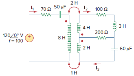
Chapter 13, Problem 81P
Use PSpice or MultiSim to find I1, I2, and I3 in the circuit of Fig. 13.142.
Expert Solution & Answer
Want to see the full answer?
Check out a sample textbook solution
Students have asked these similar questions
1) A 40?45 V voltage source is in series with a 6-ohm resistor and the parallel combination of a10-ohm resistor and an inductor with a reactance of 8-ohm. Find the equivalent current sourcecircuit
2. Find the mesh currents in the circuit shown in Fig. 13-38.
13.
Find vx
12 V
Vx
3.
University of Thi-Qar/Department of Electrical and Electronic Engineering-Lectures are prepared by M.Sc. All Kareem Page
2015
1st Stage: Fu
Homework:
Homework:
ww-
Homewor
5.1
5.5
O 10 A
6 A 4
94.37 W
10.45 W
52.9 W
Answe
vl 9.143V,
v2 =-10,286 V
Answer
Homew
Homework:
5.6
5.2
30 2
2 A G
602
102
202
10 A
Ans
Answer
4 A
67 mA
Hom
Homework:
Obtain vo in the circuit of the following figure.
5.3
30 V
20 V
4 k2 $ %
2 k2
5 k2
Answer
20 V
Homework:
Use nodal analysis to obtain vo in the circuit in below figure.
5.4
4 2
10 V
ww
12 V
22
Answer
8.727 V
ww-
Chapter 13 Solutions
Fundamentals of Electric Circuits
Ch. 13.2 - Determine the voltage Vo in the circuit of Fig....Ch. 13.2 - Determine the phasor currents I1 and I2 in the...Ch. 13.3 - Prob. 3PPCh. 13.4 - Find the input impedance of the circuit in Fig....Ch. 13.4 - For the linear transformer in Fig. 13.26(a), find...Ch. 13.4 - Solve the problem in Example 13.1 (see Fig. 13.9)...Ch. 13.5 - The primary current to an ideal transformer rated...Ch. 13.5 - In the ideal transformer circuit of Fig. 13.38,...Ch. 13.5 - Find Vo in the circuit of Fig. 13.40. Figure 13.40...Ch. 13.6 - Refer to Fig. 13.43. If the two-winding...
Ch. 13.6 - In the autotransformer circuit of Fig. 13.45, find...Ch. 13.7 - Prob. 12PPCh. 13.8 - Prob. 13PPCh. 13.9 - Refer to Fig. 13.61. Calculate the turns ratio...Ch. 13.9 - Calculate the turns ratio of an ideal transformer...Ch. 13.9 - In Example 13.17, if the eight 100-W bulbs are...Ch. 13 - Refer to the two magnetically coupled coils of...Ch. 13 - Prob. 2RQCh. 13 - Prob. 3RQCh. 13 - Prob. 4RQCh. 13 - The ideal transformer in Fig. 13.70(a) has N2/N1 =...Ch. 13 - Prob. 6RQCh. 13 - A three-winding transformer is connected as...Ch. 13 - Prob. 8RQCh. 13 - Prob. 9RQCh. 13 - Prob. 10RQCh. 13 - For the three coupled coils in Fig. 13.72,...Ch. 13 - Using Fig. 13.73, design a problem to help other...Ch. 13 - Two coils connected in series-aiding fashion have...Ch. 13 - (a) For the coupled coils in Fig. 13.74(a), show...Ch. 13 - Two coils are mutually coupled, with L1 = 50 mH,...Ch. 13 - Given the circuit shown in Fig. 13.75, determine...Ch. 13 - For the circuit in Fig. 13.76, find Vo. Figure...Ch. 13 - Find v(t) for the circuit in Fig. 13.77.Ch. 13 - Prob. 9PCh. 13 - Find vo in the circuit of Fig. 13.79. Figure 13.79...Ch. 13 - Use mesh analysis to find ix in Fig. 13.80, where...Ch. 13 - Determine the equivalent Leq in the circuit of...Ch. 13 - For the circuit in Fig. 13.82, determine the...Ch. 13 - Obtain the Thevenin equivalent circuit for the...Ch. 13 - Find the Norton equivalent for the circuit in Fig....Ch. 13 - Obtain the Norton equivalent at terminals a-b of...Ch. 13 - In the circuit of Fig. 13.86, ZL is a 15-mH...Ch. 13 - Find the Thevenin equivalent to the left of the...Ch. 13 - Determine an equivalent T-section that can be used...Ch. 13 - Determine currents I1, I2, and I3 in the circuit...Ch. 13 - Prob. 21PCh. 13 - Find current Io in the circuit of Fig. 13.91.Ch. 13 - Let is = 5 cos (100t) A. Calculate the voltage...Ch. 13 - In the circuit of Fig. 13.93, (a) find the...Ch. 13 - Prob. 25PCh. 13 - Find Io in the circuit of Fig. 13.95. Switch the...Ch. 13 - Find the average power delivered to the 50-...Ch. 13 - In the circuit of Fig. 13.97, find the value of X...Ch. 13 - Prob. 29PCh. 13 - (a) Find the input impedance of the circuit in...Ch. 13 - Using Fig. 13.100, design a problem to help other...Ch. 13 - Two linear transformers are cascaded as shown in...Ch. 13 - Determine the input impedance of the air-core...Ch. 13 - Using Fig. 13.103, design a problem to help other...Ch. 13 - Find currents I1, I2, and I3 in the circuit of...Ch. 13 - As done in Fig. 13.33, obtain the relationships...Ch. 13 - A 2402,400-V rms step-up ideal transformer...Ch. 13 - Design a problem to help other students better...Ch. 13 - A 1,200240-V rms transformer has impedance on the...Ch. 13 - The primary of an ideal transformer with a turns...Ch. 13 - Given I2 = 2 A, determine the value of Is in Fig....Ch. 13 - For the circuit in Fig. 13.107, determine the...Ch. 13 - Obtain V1 and V2 in the ideal transformer circuit...Ch. 13 - In the ideal transformer circuit of Fig. 13.109,...Ch. 13 - For the circuit in Fig. 13.110, find the value of...Ch. 13 - (a) Find I1 and I2 in the circuit of Fig. 13.111...Ch. 13 - Prob. 47PCh. 13 - Using Fig. 13.113, design a problem to help other...Ch. 13 - Find current ix in the ideal transformer circuit...Ch. 13 - Prob. 50PCh. 13 - Use the concept of reflected impedance to find the...Ch. 13 - For the circuit in Fig. 13.117, determine the...Ch. 13 - Refer to the network in Fig. 13.118. (a) Find n...Ch. 13 - A transformer is used to match an amplifier with...Ch. 13 - For the circuit in Fig. 13.120, calculate the...Ch. 13 - Find the power absorbed by the 100- resistor in...Ch. 13 - For the ideal transformer circuit of Fig. 13.122...Ch. 13 - Determine the average power absorbed by each...Ch. 13 - In the circuit of Fig. 13.124, let vs = 165...Ch. 13 - Refer to the circuit in Fig. 13.125 on the...Ch. 13 - For the circuit in Fig. 13.126, find Il, I2, and...Ch. 13 - For the network in Fig. 13.127, find: (a) the...Ch. 13 - Find the mesh currents in th circuit of Fig....Ch. 13 - For the circuit in Fig. 13.129. find the turns...Ch. 13 - Calculate the average power dissipated by the 20-...Ch. 13 - Design a problem to help other students better...Ch. 13 - An autotransformer with a 40 percent tap is...Ch. 13 - In the ideal autotransformer of Fig. 13.131,...Ch. 13 - In the circuit of Fig. 13.131, N1 = 190 turns and...Ch. 13 - In the ideal transformer circuit shown in Fig....Ch. 13 - When individuals travel, their electrical...Ch. 13 - In order to meet an emergency, three single-phase...Ch. 13 - Figure 13.135 on the next page shows a three-phase...Ch. 13 - Consider the three-phase transformer shown in Fig....Ch. 13 - A balanced three-phase transformer bank with the...Ch. 13 - Using Fig. 13.138, design a problem to help other...Ch. 13 - The three-phase system of a town distributes power...Ch. 13 - Use PSpice or MultiSim to determine the mesh...Ch. 13 - Use PSpice or MultiSim to find I1, I2, and I3 in...Ch. 13 - Prob. 80PCh. 13 - Use PSpice or MultiSim to find I1, I2, and I3 in...Ch. 13 - A stereo amplifier circuit with ail output...Ch. 13 - A transformer having 2,400 turns on the primary...Ch. 13 - A radio receiver has an input resistance of 300 ....Ch. 13 - A step-down power transformer with a turns ratio...Ch. 13 - A 240120-V rms power transformer is rated at 10...Ch. 13 - A 4-kVA, 2,400240-V rms transformer has 250 turns...Ch. 13 - A 25,000240-V rms distribution transformer has a...Ch. 13 - A 4,800-V rms transmission line feeds a...Ch. 13 - A four-winding transformer (Fig. 13.146) is often...Ch. 13 - A 440/110-V ideal transformer can be connected to...Ch. 13 - Ten bulbs in parallel are supplied by a 7,200120-V...
Knowledge Booster


Learn more about
Need a deep-dive on the concept behind this application? Look no further. Learn more about this topic, electrical-engineering and related others by exploring similar questions and additional content below.Similar questions
- Calculate the mesh currents in the circuit of Fig. 13.11.arrow_forward13. Applying Thevenin’s theorem, calculate the current (showing its direction) in the 13 ohms resistor of circuit given in Figure 13. [Ans: 168.7 V; and 8.31A]arrow_forwardIn the d.c. network shown in Fig.13.47, A is the feeding point and Is maintained at 250 V. The resistances of the various branches (go and return) are indicated in the figure. Determine the current in each branch. + 12 A 0.4 a 36 A 0.8 Q + 16 A 0.40 8A D Fig. 1347 Ans:- [AB = 144A ; BC = 2A ; DC = 5A ; AD = 13A] 0.8 a 04 aarrow_forward
- For the given figure below, answer the following. 1. Resistor values in ohms.2. Use nodal analysis to determine V1, V2, and V3.3. Use mesh analysis to determine IS and Ix.arrow_forwardFind the Thevenin equivalent for the circuit in Fig. 13.84 at terminals a-b.arrow_forward13. Find the equivalent resistance of the network shown below. + 5arrow_forward
- 21) 21. Find V₁ (jo) and V₂(jo) in terms of I, (jo) and 1₂(jw) for each circuit of Fig. 13.49. + V₁ www R₁ L₁ M FIGURE 13.49 (a) mm 1/3 R₂ + V₂ O + V₁ R₁ мет M (b) www R₂ L2 V₂ +arrow_forwardtmpFE9M/edit BOcument Atherosciorosis O science project 8th.. E Tobiloba Aderemi -. 6 Clever logo ConnectEdSingle s. E3B Algebral-G. Ha.. lel Circuits Insert Format Tools Add-ons Help Last edit was yesterday at 10:07 PM 100% Normal text Arlal BIUA 11 2 4 6. 3. In this circuit, three resistors receive the same amount of voltage (24 volts) from a single source. Calculate the amount of current "drawn" by each resistor, as well as the amount of power dissipated by each resistor: 10 ww 20 30 24 voltsarrow_forwardFundamentals of Electrical Engineering 2020/2021 Dr. Yaseen H. Tahir We can note that IL and VL are same in both cases. Example: a) Convert the current soure of Figure below to an equivalent voltage source. b) Prove your answer. (Home work) a R Rs 10KΩ 20KO 5 mAarrow_forward
- 20 log₁0|H(0)|, dB Design a circuit that has the asymptotic magnitude Bode plot shown below. Assume C1 = 0.1uF 32 12 400 4 k 40 k (0 ad/s, log scale) 40arrow_forwardFIG 1: 12 202 15 SL 13L * note: Sw1 switch 1 In problem 1 .....Compute for total resistance (Rt) , Total current (It) and V1....when SW1 is closed.arrow_forwardQ3) For the network shown in the figure below, determine the following: a) re b) Zini and Zinz c) Zoj and Zo2 d) Av1, Av2, and AvT +20 V 6.8 ka 30 kQ 6.8 ka 30 ka 0.5 pF 0.5 uF 1150 B-150 1.5 ka 50 uF 1.5 ka 50 uFarrow_forward
arrow_back_ios
SEE MORE QUESTIONS
arrow_forward_ios
Recommended textbooks for you
 Introductory Circuit Analysis (13th Edition)Electrical EngineeringISBN:9780133923605Author:Robert L. BoylestadPublisher:PEARSON
 Delmar's Standard Textbook Of ElectricityElectrical EngineeringISBN:9781337900348Author:Stephen L. HermanPublisher:Cengage Learning
 Programmable Logic ControllersElectrical EngineeringISBN:9780073373843Author:Frank D. PetruzellaPublisher:McGraw-Hill Education
 Fundamentals of Electric CircuitsElectrical EngineeringISBN:9780078028229Author:Charles K Alexander, Matthew SadikuPublisher:McGraw-Hill Education
 Electric Circuits. (11th Edition)Electrical EngineeringISBN:9780134746968Author:James W. Nilsson, Susan RiedelPublisher:PEARSON
 Engineering ElectromagneticsElectrical EngineeringISBN:9780078028151Author:Hayt, William H. (william Hart), Jr, BUCK, John A.Publisher:Mcgraw-hill Education,
Introductory Circuit Analysis (13th Edition)
Electrical Engineering
ISBN:9780133923605
Author:Robert L. Boylestad
Publisher:PEARSON
Delmar's Standard Textbook Of Electricity
Electrical Engineering
ISBN:9781337900348
Author:Stephen L. Herman
Publisher:Cengage Learning
Programmable Logic Controllers
Electrical Engineering
ISBN:9780073373843
Author:Frank D. Petruzella
Publisher:McGraw-Hill Education
Fundamentals of Electric Circuits
Electrical Engineering
ISBN:9780078028229
Author:Charles K Alexander, Matthew Sadiku
Publisher:McGraw-Hill Education
Electric Circuits. (11th Edition)
Electrical Engineering
ISBN:9780134746968
Author:James W. Nilsson, Susan Riedel
Publisher:PEARSON
Engineering Electromagnetics
Electrical Engineering
ISBN:9780078028151
Author:Hayt, William H. (william Hart), Jr, BUCK, John A.
Publisher:Mcgraw-hill Education,
Mesh Current Problems in Circuit Analysis - Electrical Circuits Crash Course - Beginners Electronics; Author: Math and Science;https://www.youtube.com/watch?v=DYg8B-ElK0s;License: Standard Youtube License