
Fundamentals of Electric Circuits
6th Edition
ISBN: 9780078028229
Author: Charles K Alexander, Matthew Sadiku
Publisher: McGraw-Hill Education
expand_more
expand_more
format_list_bulleted
Concept explainers
Videos
Textbook Question
Chapter 13, Problem 71P
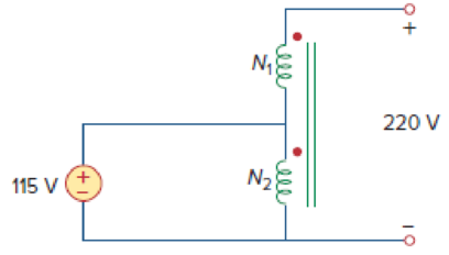
When individuals travel, their electrical appliances need to have converters to match the voltages required by their appliances to the local voltage available to power their appliances. Today these converters use power electronics to convert voltages. In the past these converters were autotransformers. The autotransformer shown in Fig. 13.134 is used to convert 115 to 220 V. What is the value of the turns? If the maximum current available from the 115 V source is 15 A, what will be the maximum current available for the 220-V appliance?
Expert Solution & Answer
Want to see the full answer?
Check out a sample textbook solution
Students have asked these similar questions
Your aunt living in the USA sent an appliance that has impedance equal to 10 + j3 22 at 60 Hz.
She instructed you to purchase a 220 V to 110 V transformer to step down the voltage since the
appliance is rated 110 V. The cord that you used to connect the 220 V side of the transformer to
the convenience outlet has a total impedance of 1 + j0.5 Q. You measured the voltage at the
outlet and the value is 220 Vrms.
The equivalent circuit is shown below:
j0.5 Q
19
m
IL
220 V rms
10+ j3 VL
Ω
220 V : 110 V
Solve for the voltage across the appliance and the current through it by either
A. Referring the appliance to the transformer primary, OR
B. Referring the source and cord impedance to the transformer secondary.
Assign the convenience outlet voltage as the reference phasor, i.e. at 0°.
Choose only one method above. After choosing,
1. Draw the circuit that would solve for V₁ and ₁. Compute all referred values and label all
components.
2. Solve for V₁ and T.
QUESTION 3
A 1KVA ideal transformer supplied with 120V RMS and connected to a 1kQ load draws 100mA RMS of current on the secondary. What load must be connected in order to draw full power?
O 1000
O 1.50
O 100
O 1kQ
Your aunt living in the USA sent an appliance that has impedance equal to 10 + j3 2 at 60 Hz.
She instructed you to purchase a 220 V to 110 V transformer to step down the voltage since the
appliance is rated 110 V. The cord that you used to connect the 220 V side of the transformer to
the convenience outlet has a total impedance of 1 + j0.5 Q. You measured the voltage at the
outlet and the value is 220 Vrms.
The equivalent circuit is shown below:
j0.5 Ω
1Ω
mm
N220 V rms
10 + j3 V₁
Ω
220 V 110 V
Solve for the voltage across the appliance and the current through it by either
A. Referring the appliance to the transformer primary, OR
B. Referring the source and cord impedance to the transformer secondary.
Assign the convenience outlet voltage as the reference phasor, i.e. at 0°.
Choose only one method above. After choosing,
1. Draw the circuit that would solve for V₁ and I. Compute all referred values and label all
components.
2. Solve for V₁ and I₁.
S
+
I
Chapter 13 Solutions
Fundamentals of Electric Circuits
Ch. 13.2 - Determine the voltage Vo in the circuit of Fig....Ch. 13.2 - Determine the phasor currents I1 and I2 in the...Ch. 13.3 - Prob. 3PPCh. 13.4 - Find the input impedance of the circuit in Fig....Ch. 13.4 - For the linear transformer in Fig. 13.26(a), find...Ch. 13.4 - Solve the problem in Example 13.1 (see Fig. 13.9)...Ch. 13.5 - The primary current to an ideal transformer rated...Ch. 13.5 - In the ideal transformer circuit of Fig. 13.38,...Ch. 13.5 - Find Vo in the circuit of Fig. 13.40. Figure 13.40...Ch. 13.6 - Refer to Fig. 13.43. If the two-winding...
Ch. 13.6 - In the autotransformer circuit of Fig. 13.45, find...Ch. 13.7 - Prob. 12PPCh. 13.8 - Prob. 13PPCh. 13.9 - Refer to Fig. 13.61. Calculate the turns ratio...Ch. 13.9 - Calculate the turns ratio of an ideal transformer...Ch. 13.9 - In Example 13.17, if the eight 100-W bulbs are...Ch. 13 - Refer to the two magnetically coupled coils of...Ch. 13 - Prob. 2RQCh. 13 - Prob. 3RQCh. 13 - Prob. 4RQCh. 13 - The ideal transformer in Fig. 13.70(a) has N2/N1 =...Ch. 13 - Prob. 6RQCh. 13 - A three-winding transformer is connected as...Ch. 13 - Prob. 8RQCh. 13 - Prob. 9RQCh. 13 - Prob. 10RQCh. 13 - For the three coupled coils in Fig. 13.72,...Ch. 13 - Using Fig. 13.73, design a problem to help other...Ch. 13 - Two coils connected in series-aiding fashion have...Ch. 13 - (a) For the coupled coils in Fig. 13.74(a), show...Ch. 13 - Two coils are mutually coupled, with L1 = 50 mH,...Ch. 13 - Given the circuit shown in Fig. 13.75, determine...Ch. 13 - For the circuit in Fig. 13.76, find Vo. Figure...Ch. 13 - Find v(t) for the circuit in Fig. 13.77.Ch. 13 - Prob. 9PCh. 13 - Find vo in the circuit of Fig. 13.79. Figure 13.79...Ch. 13 - Use mesh analysis to find ix in Fig. 13.80, where...Ch. 13 - Determine the equivalent Leq in the circuit of...Ch. 13 - For the circuit in Fig. 13.82, determine the...Ch. 13 - Obtain the Thevenin equivalent circuit for the...Ch. 13 - Find the Norton equivalent for the circuit in Fig....Ch. 13 - Obtain the Norton equivalent at terminals a-b of...Ch. 13 - In the circuit of Fig. 13.86, ZL is a 15-mH...Ch. 13 - Find the Thevenin equivalent to the left of the...Ch. 13 - Determine an equivalent T-section that can be used...Ch. 13 - Determine currents I1, I2, and I3 in the circuit...Ch. 13 - Prob. 21PCh. 13 - Find current Io in the circuit of Fig. 13.91.Ch. 13 - Let is = 5 cos (100t) A. Calculate the voltage...Ch. 13 - In the circuit of Fig. 13.93, (a) find the...Ch. 13 - Prob. 25PCh. 13 - Find Io in the circuit of Fig. 13.95. Switch the...Ch. 13 - Find the average power delivered to the 50-...Ch. 13 - In the circuit of Fig. 13.97, find the value of X...Ch. 13 - Prob. 29PCh. 13 - (a) Find the input impedance of the circuit in...Ch. 13 - Using Fig. 13.100, design a problem to help other...Ch. 13 - Two linear transformers are cascaded as shown in...Ch. 13 - Determine the input impedance of the air-core...Ch. 13 - Using Fig. 13.103, design a problem to help other...Ch. 13 - Find currents I1, I2, and I3 in the circuit of...Ch. 13 - As done in Fig. 13.33, obtain the relationships...Ch. 13 - A 2402,400-V rms step-up ideal transformer...Ch. 13 - Design a problem to help other students better...Ch. 13 - A 1,200240-V rms transformer has impedance on the...Ch. 13 - The primary of an ideal transformer with a turns...Ch. 13 - Given I2 = 2 A, determine the value of Is in Fig....Ch. 13 - For the circuit in Fig. 13.107, determine the...Ch. 13 - Obtain V1 and V2 in the ideal transformer circuit...Ch. 13 - In the ideal transformer circuit of Fig. 13.109,...Ch. 13 - For the circuit in Fig. 13.110, find the value of...Ch. 13 - (a) Find I1 and I2 in the circuit of Fig. 13.111...Ch. 13 - Prob. 47PCh. 13 - Using Fig. 13.113, design a problem to help other...Ch. 13 - Find current ix in the ideal transformer circuit...Ch. 13 - Prob. 50PCh. 13 - Use the concept of reflected impedance to find the...Ch. 13 - For the circuit in Fig. 13.117, determine the...Ch. 13 - Refer to the network in Fig. 13.118. (a) Find n...Ch. 13 - A transformer is used to match an amplifier with...Ch. 13 - For the circuit in Fig. 13.120, calculate the...Ch. 13 - Find the power absorbed by the 100- resistor in...Ch. 13 - For the ideal transformer circuit of Fig. 13.122...Ch. 13 - Determine the average power absorbed by each...Ch. 13 - In the circuit of Fig. 13.124, let vs = 165...Ch. 13 - Refer to the circuit in Fig. 13.125 on the...Ch. 13 - For the circuit in Fig. 13.126, find Il, I2, and...Ch. 13 - For the network in Fig. 13.127, find: (a) the...Ch. 13 - Find the mesh currents in th circuit of Fig....Ch. 13 - For the circuit in Fig. 13.129. find the turns...Ch. 13 - Calculate the average power dissipated by the 20-...Ch. 13 - Design a problem to help other students better...Ch. 13 - An autotransformer with a 40 percent tap is...Ch. 13 - In the ideal autotransformer of Fig. 13.131,...Ch. 13 - In the circuit of Fig. 13.131, N1 = 190 turns and...Ch. 13 - In the ideal transformer circuit shown in Fig....Ch. 13 - When individuals travel, their electrical...Ch. 13 - In order to meet an emergency, three single-phase...Ch. 13 - Figure 13.135 on the next page shows a three-phase...Ch. 13 - Consider the three-phase transformer shown in Fig....Ch. 13 - A balanced three-phase transformer bank with the...Ch. 13 - Using Fig. 13.138, design a problem to help other...Ch. 13 - The three-phase system of a town distributes power...Ch. 13 - Use PSpice or MultiSim to determine the mesh...Ch. 13 - Use PSpice or MultiSim to find I1, I2, and I3 in...Ch. 13 - Prob. 80PCh. 13 - Use PSpice or MultiSim to find I1, I2, and I3 in...Ch. 13 - A stereo amplifier circuit with ail output...Ch. 13 - A transformer having 2,400 turns on the primary...Ch. 13 - A radio receiver has an input resistance of 300 ....Ch. 13 - A step-down power transformer with a turns ratio...Ch. 13 - A 240120-V rms power transformer is rated at 10...Ch. 13 - A 4-kVA, 2,400240-V rms transformer has 250 turns...Ch. 13 - A 25,000240-V rms distribution transformer has a...Ch. 13 - A 4,800-V rms transmission line feeds a...Ch. 13 - A four-winding transformer (Fig. 13.146) is often...Ch. 13 - A 440/110-V ideal transformer can be connected to...Ch. 13 - Ten bulbs in parallel are supplied by a 7,200120-V...
Knowledge Booster


Learn more about
Need a deep-dive on the concept behind this application? Look no further. Learn more about this topic, electrical-engineering and related others by exploring similar questions and additional content below.Similar questions
- Your aunt living in the USA sent an appliance that has impedance equal to 10+ j3 2 at 60 Hz. She instructed you to purchase a 220 V to 110 V transformer to step down the voltage since the appliance is rated 110 V. The cord that you used to connect the 220 V side of the transformer to the convenience outlet has a total impedance of 1 + j0.5 Q. You measured the voltage at the outlet and the value is 220 Vrms. The equivalent circuit is shown below: 1Ω mm ĪT + 10+j3 VL 220 V rms Ω 220 V : 110 V Solve for the voltage across the appliance and the current through it by either A. Referring the appliance to the transformer primary, OR B. Referring the source and cord impedance to the transformer secondary. Assign the convenience outlet voltage as the reference phasor, i.e. at 0°. Choose only one method above. After choosing, 1. Draw the circuit that would solve for V₁ and T. Compute all referred values and label all components. 2. Solve for V and I. j0.5 Q +arrow_forwardYour aunt living in the USA sent an appliance that has impedance equal to 10 + j3 2 at 60 Hz. She instructed you to purchase a 220 V to 110 V transformer to step down the voltage since the appliance is rated 110 V. The cord that you used to connect the 220 V side of the transformer to the convenience outlet has a total impedance of 1 + j0.5 Q. You measured the voltage at the outlet and the value is 220 Vrms. The equivalent circuit is shown below: 1 Ω m T 220 V rms 10+ j3 V Ω 220 V : 110 V Solve for the voltage across the appliance and the current through it by either A. Referring the appliance to the transformer primary, OR B. Referring the source and cord impedance to the transformer secondary. Assign the convenience outlet voltage as the reference phasor, i.e. at 0°. Choose only one method above. After choosing, j0.5 Q +arrow_forwardYour aunt living in the USA sent an appliance that has impedance equal to 10 + j3 2 at 60 Hz. She instructed you to purchase a 220 V to 110 V transformer to step down the voltage since the appliance is rated 110 V. The cord that you used to connect the 220 V side of the transformer to the convenience outlet has a total impedance of 1 + j0.5 Q. You measured the voltage at the outlet and the value is 220 Vrms. The equivalent circuit is shown below: j0.5 Q 19 ww + (N) 220 V rms 10+ j3 VL Ω 220 V : 110 V Solve for the voltage across the appliance and the current through it by either A. Referring the appliance to the transformer primary, OR B. Referring the source and cord impedance to the transformer secondary. Assign the convenience outlet voltage as the reference phasor, i.e. at 0°. Choose only one method above. After choosing, 1. Draw the circuit that would solve for V₁ and T. Compute all referred values and label all components. 2. Solve for V and I.arrow_forward
- 10. In a step-down transformer, the number of turns in the secondary coil is 20 and the number of turns in the primary coil is 100. If the voltage applied to the primary coil is 120 V, then what is the voltage output from the secondary coil? a) 24 V b) 12 V c) 6 V d) 18 Varrow_forward5. You need a transformer that will draw 15 W of power from a 220 V power line, stepping the voltage down to 6.0 V. a. What is the current in the secondary coil? b. What should be the resistance of the secondary circuit? c. What will be the equivalent resistance of the input circuit?arrow_forwardYour aunt living in the USA sent an appliance that has impedance equal to 10+ j3 2 at 60 Hz. She instructed you to purchase a 220 V to 110 V transformer to step down the voltage since the appliance is rated 110 V. The cord that you used to connect the 220 V side of the transformer to the convenience outlet has a total impedance of 1 + j0.5 Q. You measured the voltage at the outlet and the value is 220 Vrms. The equivalent circuit is shown below: 1Ω m IL + (N) 220 V rms 10+ j3 VL 22 220 V 110 V Solve for the voltage across the appliance and the current through it by either A. Referring the appliance to the transformer primary, OR B. Referring the source and cord impedance to the transformer secondary. Assign the convenience outlet voltage as the reference phasor, i.e. at 0°. Choose only one method above. After choosing, 1. Draw the circuit that would solve for V₁ and T₁. Compute all referred values and label all components. j0.5 Ωarrow_forward
- A power transformer with a voltage rating of 12500:240 V has a primary current rating of50 A. Find the transformer kVA rating and the secondary current rating if the 240 V is thesecondary voltage rating.arrow_forwardA 5KVA ideal transformer supplied with 120V RMS and connected to a 1kQ load draws 2A RMS of current on the secondary. What load must be connected in order to draw full power? 1kQ 2.5kQ 8000 3.50arrow_forward> 7. A step-down transformer delivers 5 V @ 2 A. If the pri- mary is connected to a 120 Vac source, what is the value of primary current?arrow_forward
- The primary of a current transformer takes 1 A at a power factor of 0.4 when it is connected across a 200-V, 50Hz supply and the secondary is on open circuit. The number of turns on the primary is twice that on the secondary. A load taking 50 A at a lagging power factor of 0.8 is now connected across the secondary. What is now the value of primary current?arrow_forwardA 6 KVA step-up transformer having a turns ratio of 1:4 has a primary voltage of 1000V.calculate the value of the secondary current. Select one: O a. 20 A O b. 4 A c. 1.5 A O d. 1 Aarrow_forwardIn a facility for transformer testing and parameter evaluation, you have been hired as an Electrical Engineer. A step-down transformer with a turn ratio of 10 whose primary is connected to 2200 V has an apparent power rating of 20 KVA. A technician performed the open and closed circuit tests and provided you with the following data. O.C Test (Performed on LV Side): 220 V, 4.2 A, 148 W S.C Test (Performed on HV Side): 86 V, 10.5 A, 360 W You have two major tasks to perform: a) Estimate the parameter of the corresponding equivalent circuit for this transformer with reference to low voltage side b) Also, when this transformer is working at a fully loaded condition with 0.8 PF lagging, calculate the voltage regulation.arrow_forward
arrow_back_ios
SEE MORE QUESTIONS
arrow_forward_ios
Recommended textbooks for you
 Introductory Circuit Analysis (13th Edition)Electrical EngineeringISBN:9780133923605Author:Robert L. BoylestadPublisher:PEARSON
 Delmar's Standard Textbook Of ElectricityElectrical EngineeringISBN:9781337900348Author:Stephen L. HermanPublisher:Cengage Learning
 Programmable Logic ControllersElectrical EngineeringISBN:9780073373843Author:Frank D. PetruzellaPublisher:McGraw-Hill Education
 Fundamentals of Electric CircuitsElectrical EngineeringISBN:9780078028229Author:Charles K Alexander, Matthew SadikuPublisher:McGraw-Hill Education
 Electric Circuits. (11th Edition)Electrical EngineeringISBN:9780134746968Author:James W. Nilsson, Susan RiedelPublisher:PEARSON
 Engineering ElectromagneticsElectrical EngineeringISBN:9780078028151Author:Hayt, William H. (william Hart), Jr, BUCK, John A.Publisher:Mcgraw-hill Education,
Introductory Circuit Analysis (13th Edition)
Electrical Engineering
ISBN:9780133923605
Author:Robert L. Boylestad
Publisher:PEARSON
Delmar's Standard Textbook Of Electricity
Electrical Engineering
ISBN:9781337900348
Author:Stephen L. Herman
Publisher:Cengage Learning
Programmable Logic Controllers
Electrical Engineering
ISBN:9780073373843
Author:Frank D. Petruzella
Publisher:McGraw-Hill Education
Fundamentals of Electric Circuits
Electrical Engineering
ISBN:9780078028229
Author:Charles K Alexander, Matthew Sadiku
Publisher:McGraw-Hill Education
Electric Circuits. (11th Edition)
Electrical Engineering
ISBN:9780134746968
Author:James W. Nilsson, Susan Riedel
Publisher:PEARSON
Engineering Electromagnetics
Electrical Engineering
ISBN:9780078028151
Author:Hayt, William H. (william Hart), Jr, BUCK, John A.
Publisher:Mcgraw-hill Education,
TRANSFORMERS - What They Are, How They Work, How Electricians Size Them; Author: Electrician U;https://www.youtube.com/watch?v=tXPy4OE7ApE;License: Standard Youtube License