
Electronics Fundamentals: Circuits, Devices & Applications
8th Edition
ISBN: 9780135072950
Author: Thomas L. Floyd, David Buchla
Publisher: Prentice Hall
expand_more
expand_more
format_list_bulleted
Concept explainers
Videos
Textbook Question
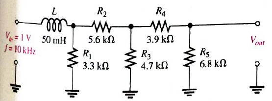
Chapter 12, Problem 40P
Determine the phase shift and attenuation
Expert Solution & Answer
Want to see the full answer?
Check out a sample textbook solution
Students have asked these similar questions
9. Figure 12–62 shows the output voltage of an op-amp in response to a step input. What is the
slew rate?
V out
FIGURE 12–62
+12 V -
15 μ
-12 V-
11. Identify each of the op-amp configurations in Figure 12–63.
The input voltage to chopper circuit with a switching frequency of 100 Hz and TOn time as 2.0 ms is 10 V. The average DC output is:
O 4V
O 2V
O 6V
O 8V
13. For the amplifier in Figure 12-63, determine the following:
(a) AND
(b) Vou
(c) V
10mV rms
R
560 kN
R
1.5 kN
Chapter 12 Solutions
Electronics Fundamentals: Circuits, Devices & Applications
Ch. 12 - In an ac circuit where R=XL, the phase angle is...Ch. 12 - Prob. 2TFQCh. 12 - In an ac series RL circuit, the current and...Ch. 12 - In an ac parallel RL circuit, the inductive...Ch. 12 - In an ac parallel RL circuit, the voltage across...Ch. 12 - The unit siemens is used to measure both...Ch. 12 - Prob. 7TFQCh. 12 - If the power factor of a circuit is 0.5, the...Ch. 12 - Prob. 9TFQCh. 12 - Prob. 10TFQ
Ch. 12 - In a series RL circuit, the resistor voltage Leads...Ch. 12 - Prob. 2STCh. 12 - Prob. 3STCh. 12 - If the frequency is doubled and the resistance is...Ch. 12 - Prob. 5STCh. 12 - Prob. 6STCh. 12 - Prob. 7STCh. 12 - Prob. 8STCh. 12 - Prob. 9STCh. 12 - Prob. 10STCh. 12 - Prob. 11STCh. 12 - Prob. 12STCh. 12 - If a load is purely inductive and the reactive...Ch. 12 - Prob. 14STCh. 12 - Prob. 15STCh. 12 - Determine the cause for each set of symptoms....Ch. 12 - Determine the cause for each set of symptoms....Ch. 12 - Prob. 3TSCCh. 12 - Prob. 4TSCCh. 12 - Prob. 5TSCCh. 12 - Prob. 1PCh. 12 - Prob. 2PCh. 12 - Find the impedance of each circuit in Figure...Ch. 12 - Determine the impedance and phase angle in each...Ch. 12 - In Figure 12-52, determine the impedance at each...Ch. 12 - Determine the values of R and XL in a series RL...Ch. 12 - If the frequency of the source is increased to 1...Ch. 12 - Determine the voltage across the total resistance...Ch. 12 - Find the current for each circuit of Figure 12-50.Ch. 12 - Calculate the total current in each circuit of...Ch. 12 - Determine for the cicutit in Figure 12-53.Ch. 12 - If the inductance in Figure 12-53 is doubled, does...Ch. 12 - Draw the waveforms for Vs,VRandVL in Figure 12-53....Ch. 12 - For the circuit in Figure 12-54, find VRandVL for...Ch. 12 - For the lag circuit in Figure 12-55, determine the...Ch. 12 - Repeat Problem 15 for the lead circuit in Figure...Ch. 12 - What is the impedance for the circuit in Figure...Ch. 12 - Repeat Problem 17 for the following frequencies:...Ch. 12 - At what frequecy does XL equal R in Figure 12-57?Ch. 12 - Find the total current and each branch current in...Ch. 12 - Determine the following quantities in Figure...Ch. 12 - Convert the circuit in Figure 12-60 to an...Ch. 12 - Determine the voltage across each element in...Ch. 12 - Is the circuit in Figure 12-61 predominantly...Ch. 12 - Find the current in each branch and the total...Ch. 12 - In a certain RL circuit, the true power is 100 mW,...Ch. 12 - Determine the true power and the reactive power in...Ch. 12 - What is the power factor in Figure 12-58?Ch. 12 - Determine Ptrue,Pr,Pa, and PF for the circuit in...Ch. 12 - Plot the response curve for the circuit in Figure...Ch. 12 - Using the same procedure as in Problem 30, plot...Ch. 12 - Draw the voltage phasor diagram for each circuit...Ch. 12 - Prob. 33PCh. 12 - Prob. 34PCh. 12 - Determine the voltage across the inductors in...Ch. 12 - Is the circuit in Figure 12-64 predominantly...Ch. 12 - Find the total current in Figure 12-64.Ch. 12 - Determine the phase shift and attenuation...Ch. 12 - Design an ideal inductive switching circuit that...Ch. 12 - Prob. 44PCh. 12 - Prob. 45PCh. 12 - Prob. 46PCh. 12 - Prob. 47PCh. 12 - Open file P12-48. Determine if there is a fault...Ch. 12 - Prob. 49P
Knowledge Booster


Learn more about
Need a deep-dive on the concept behind this application? Look no further. Learn more about this topic, electrical-engineering and related others by exploring similar questions and additional content below.Similar questions
- The circuit in Figure 24-2 is connected to a 120-V, 60-Hz line. The resistor has a resistance of 36 , the inductor has an inductive reactance of 40 , and the capacitor has a capacitive reactance of 50 . ET120VITZVAPFERIRR36PELILXL40VARsLLECICXC50VARsCCarrow_forwarda capacitor and a resistor are connected in parellel to a 120 v 60 hz line the resistor has a resistance of 40 ohms and the capacitor has a capacitance of 132.6 uf what is the total current flow through the circuit. what is the impedence and the power factor and how many degrees out of phase are the current and voltage out phase with eachother.arrow_forwardThe equivalent inductance seen at terminal AB in figure isarrow_forward
- 2. Find the current delivered by the alternating current source to the circuit in the adjacent figure when (a) the frequency is very low and (b) when the frequency is very high. 100 (2 M-0000 10 Vrms www 50 0 - 20 Farrow_forwardWhat is the voltage between nodes A and B in each circuit in Figure 12–73?arrow_forwardHw MANY MODES, LOOP, MEH IN THE FIEUREarrow_forward
- When in forward biased, what have you noticed when you change the source voltage from 0V to +20V? When in reverse biased, what have you noticed when changing the source voltage from 0 V to -15V?arrow_forwardDraw the output voltage waveform for the following circuit and find the values of Vdc and Idc R3 D3 1kQ V1 R1 12Vrms 50HZ 0° R4 1kQ 1kQarrow_forward17. If a signal voltage of 10 mV rms is applied to each amplifier in Figure 12–66, what are the out- put voltages and what is their phase relationship with inputs? 1.0 MO R 47 karrow_forward
- 1.Using the simulator of your choice simulate and screenshot the output voltage wave form for each circuit. +50 V R +5 V Vin Vout R- 47 0 3.3 kN Vin V out -50 V -5 V B Aarrow_forwardCalculate circuit values below. How does the total circuit impedence change as the frequency increases from 500 HZ to 50 Khz? How does the total current change as those frequencies increase?arrow_forward(a) An AC triangular waveform with peak values of ±2V is used as an input to a comparator. The outputs of the comparator are VOH=+5V, VOL=-5V 4 Draw a waveform of the output of the comparator when an inverting circuit in Figure 5 is used. (i) Vi - 20 Vo 20 60 Figure 5arrow_forward
arrow_back_ios
SEE MORE QUESTIONS
arrow_forward_ios
Recommended textbooks for you
 Delmar's Standard Textbook Of ElectricityElectrical EngineeringISBN:9781337900348Author:Stephen L. HermanPublisher:Cengage Learning
Delmar's Standard Textbook Of Electricity
Electrical Engineering
ISBN:9781337900348
Author:Stephen L. Herman
Publisher:Cengage Learning
Capacitors Explained - The basics how capacitors work working principle; Author: The Engineering Mindset;https://www.youtube.com/watch?v=X4EUwTwZ110;License: Standard YouTube License, CC-BY