
Electronics Fundamentals: Circuits, Devices & Applications
8th Edition
ISBN: 9780135072950
Author: Thomas L. Floyd, David Buchla
Publisher: Prentice Hall
expand_more
expand_more
format_list_bulleted
Videos
Textbook Question
Chapter 12, Problem 13P
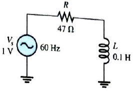
Draw the waveforms for
Expert Solution & Answer
Want to see the full answer?
Check out a sample textbook solution
Students have asked these similar questions
a capacitor and a resistor are connected in parellel to a 120 v 60 hz line the resistor has a resistance of 40 ohms and the capacitor has a capacitance of 132.6 uf what is the total current flow through the circuit. what is the impedence and the power factor and how many degrees out of phase are the current and voltage out phase with eachother.
Closed loop poles in a second order system -8 + 6j and -8-6j then what is the natural frequency of the system?
The equivalent inductance seen at terminal AB in figure is
Chapter 12 Solutions
Electronics Fundamentals: Circuits, Devices & Applications
Ch. 12 - In an ac circuit where R=XL, the phase angle is...Ch. 12 - Prob. 2TFQCh. 12 - In an ac series RL circuit, the current and...Ch. 12 - In an ac parallel RL circuit, the inductive...Ch. 12 - In an ac parallel RL circuit, the voltage across...Ch. 12 - The unit siemens is used to measure both...Ch. 12 - Prob. 7TFQCh. 12 - If the power factor of a circuit is 0.5, the...Ch. 12 - Prob. 9TFQCh. 12 - Prob. 10TFQ
Ch. 12 - In a series RL circuit, the resistor voltage Leads...Ch. 12 - Prob. 2STCh. 12 - Prob. 3STCh. 12 - If the frequency is doubled and the resistance is...Ch. 12 - Prob. 5STCh. 12 - Prob. 6STCh. 12 - Prob. 7STCh. 12 - Prob. 8STCh. 12 - Prob. 9STCh. 12 - Prob. 10STCh. 12 - Prob. 11STCh. 12 - Prob. 12STCh. 12 - If a load is purely inductive and the reactive...Ch. 12 - Prob. 14STCh. 12 - Prob. 15STCh. 12 - Determine the cause for each set of symptoms....Ch. 12 - Determine the cause for each set of symptoms....Ch. 12 - Prob. 3TSCCh. 12 - Prob. 4TSCCh. 12 - Prob. 5TSCCh. 12 - Prob. 1PCh. 12 - Prob. 2PCh. 12 - Find the impedance of each circuit in Figure...Ch. 12 - Determine the impedance and phase angle in each...Ch. 12 - In Figure 12-52, determine the impedance at each...Ch. 12 - Determine the values of R and XL in a series RL...Ch. 12 - If the frequency of the source is increased to 1...Ch. 12 - Determine the voltage across the total resistance...Ch. 12 - Find the current for each circuit of Figure 12-50.Ch. 12 - Calculate the total current in each circuit of...Ch. 12 - Determine for the cicutit in Figure 12-53.Ch. 12 - If the inductance in Figure 12-53 is doubled, does...Ch. 12 - Draw the waveforms for Vs,VRandVL in Figure 12-53....Ch. 12 - For the circuit in Figure 12-54, find VRandVL for...Ch. 12 - For the lag circuit in Figure 12-55, determine the...Ch. 12 - Repeat Problem 15 for the lead circuit in Figure...Ch. 12 - What is the impedance for the circuit in Figure...Ch. 12 - Repeat Problem 17 for the following frequencies:...Ch. 12 - At what frequecy does XL equal R in Figure 12-57?Ch. 12 - Find the total current and each branch current in...Ch. 12 - Determine the following quantities in Figure...Ch. 12 - Convert the circuit in Figure 12-60 to an...Ch. 12 - Determine the voltage across each element in...Ch. 12 - Is the circuit in Figure 12-61 predominantly...Ch. 12 - Find the current in each branch and the total...Ch. 12 - In a certain RL circuit, the true power is 100 mW,...Ch. 12 - Determine the true power and the reactive power in...Ch. 12 - What is the power factor in Figure 12-58?Ch. 12 - Determine Ptrue,Pr,Pa, and PF for the circuit in...Ch. 12 - Plot the response curve for the circuit in Figure...Ch. 12 - Using the same procedure as in Problem 30, plot...Ch. 12 - Draw the voltage phasor diagram for each circuit...Ch. 12 - Prob. 33PCh. 12 - Prob. 34PCh. 12 - Determine the voltage across the inductors in...Ch. 12 - Is the circuit in Figure 12-64 predominantly...Ch. 12 - Find the total current in Figure 12-64.Ch. 12 - Determine the phase shift and attenuation...Ch. 12 - Design an ideal inductive switching circuit that...Ch. 12 - Prob. 44PCh. 12 - Prob. 45PCh. 12 - Prob. 46PCh. 12 - Prob. 47PCh. 12 - Open file P12-48. Determine if there is a fault...Ch. 12 - Prob. 49P
Knowledge Booster


Learn more about
Need a deep-dive on the concept behind this application? Look no further. Learn more about this topic, electrical-engineering and related others by exploring similar questions and additional content below.Similar questions
- P In RL series circuit, voltage across resistor is 6V and voltage across inductor is 8V. Power factor of the circuit isarrow_forwardWhat will be magnitude of the total circuit impedance of a series LR circuit excited by a 100 Hz ac source? The resistance is 40 ohm and the inductance is 4 mF.arrow_forward12. A series RC circuit contains two resistors and two capacitors. The resistors are 68 N and 56 2. The capacitors have capacitive reactances of 66 2 and 33 2. The applied voltage is 240 V. What is the voltage drop on the 56 Q resistor? a. 39.83 V b. 49.91 V c. 84.70 V d. 102.85 V cronta apong nac.couqarrow_forward
- QUESTION 6 A resistor, a capacitor, and an inductor are connected in series with a mystery component. The resistor has a resistance of 1000, the capacitor has a reactance of 5000, and the inductor has a reactance of 2000. The total impedance of the circuit is 100-j4000. What is the mystery component? O there is no mystery component O inductor O resistor O capacitorarrow_forwardr in the figure below is to reject a 300-Hz sinusoid while passing othearrow_forwardDescribe what happens to the current in this RL series circuit as the frequency increases. Explain in general terms why the observed change should occur.arrow_forward
- 3. An RLC series circuit has a resistor with a power consumption of 124 watts. The induc- tor has a reactive power of 366 VARST, and the capacitor has a reactive power of 288 VARSC. What is the circuit power factor?arrow_forwardThe power factor of a D.C. circuit is always Select one: O a Greater than unity Ob. There in no power factor for DC Oc 1 Od oarrow_forwardQ6. Calculate the total current in the circuit below if the circuit is powered by the sine wave voltage source of 150 Vm and frequency 60 Hz. Draw the current phasor diagram and determine if this circuit fulfils the criteria of resonance. Vm Sine 60 Hz C L1 0.7 H L2 0.5 H relee cele Figure Q6 C1 5.1 mF C2 0.12 mF R1 120 22 R2 330 Ωarrow_forward
- Calculate the total current in the circuit below if the circuit is powered by the sine wave voltage source of 150 Vm and frequency 60 Hz. Draw the current phasor diagram and determine if this circuit fulfils the criteria of resonance. Vm Sine 60 Hz LI 0.7 H L2 0.5 H rele rele Figure Q6 C1 5.1 mF C2 -0.12 mF R1 120 Ω R2 330 Ωarrow_forward12. A series RC circuit contains two resistors and two capacitors. The resistors are 68 N and 56 2. The capacitors have capacitive reactances of 66 2 and 33 2. The applied voltage is 240 V. What is the voltage drop on the 56 N resistor? a. 39.83 V b. 49.91 V c. 84.70 V d. 102.85 Varrow_forwardIn a series R–L circuit the p.d. across the resistance R is 12V and the p.d. across the inductance L is 5V. Find the supply voltage and the phase angle between current and voltagearrow_forward
arrow_back_ios
SEE MORE QUESTIONS
arrow_forward_ios
Recommended textbooks for you
 Delmar's Standard Textbook Of ElectricityElectrical EngineeringISBN:9781337900348Author:Stephen L. HermanPublisher:Cengage Learning
Delmar's Standard Textbook Of Electricity
Electrical Engineering
ISBN:9781337900348
Author:Stephen L. Herman
Publisher:Cengage Learning
Inductors Explained - The basics how inductors work working principle; Author: The Engineering Mindset;https://www.youtube.com/watch?v=KSylo01n5FY;License: Standard Youtube License