
Electronics Fundamentals: Circuits, Devices & Applications
8th Edition
ISBN: 9780135072950
Author: Thomas L. Floyd, David Buchla
Publisher: Prentice Hall
expand_more
expand_more
format_list_bulleted
Videos
Textbook Question
Chapter 12, Problem 9P
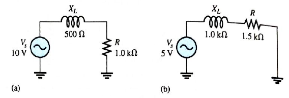
Find the current for each circuit of Figure 12-50.
Expert Solution & Answer
Want to see the full answer?
Check out a sample textbook solution
Students have asked these similar questions
please finish this and do part d
Calculate the VOLTAGE and CURRENT of each component C1, C2, L1, R1, R2 separately
With a AC voltage source of 0.4V
Please do not work with equivalent values do each one seperatly
What should be Rl and what is Pmax in order to transfer maximum power from the source to the load.
Chapter 12 Solutions
Electronics Fundamentals: Circuits, Devices & Applications
Ch. 12 - In an ac circuit where R=XL, the phase angle is...Ch. 12 - Prob. 2TFQCh. 12 - In an ac series RL circuit, the current and...Ch. 12 - In an ac parallel RL circuit, the inductive...Ch. 12 - In an ac parallel RL circuit, the voltage across...Ch. 12 - The unit siemens is used to measure both...Ch. 12 - Prob. 7TFQCh. 12 - If the power factor of a circuit is 0.5, the...Ch. 12 - Prob. 9TFQCh. 12 - Prob. 10TFQ
Ch. 12 - In a series RL circuit, the resistor voltage Leads...Ch. 12 - Prob. 2STCh. 12 - Prob. 3STCh. 12 - If the frequency is doubled and the resistance is...Ch. 12 - Prob. 5STCh. 12 - Prob. 6STCh. 12 - Prob. 7STCh. 12 - Prob. 8STCh. 12 - Prob. 9STCh. 12 - Prob. 10STCh. 12 - Prob. 11STCh. 12 - Prob. 12STCh. 12 - If a load is purely inductive and the reactive...Ch. 12 - Prob. 14STCh. 12 - Prob. 15STCh. 12 - Determine the cause for each set of symptoms....Ch. 12 - Determine the cause for each set of symptoms....Ch. 12 - Prob. 3TSCCh. 12 - Prob. 4TSCCh. 12 - Prob. 5TSCCh. 12 - Prob. 1PCh. 12 - Prob. 2PCh. 12 - Find the impedance of each circuit in Figure...Ch. 12 - Determine the impedance and phase angle in each...Ch. 12 - In Figure 12-52, determine the impedance at each...Ch. 12 - Determine the values of R and XL in a series RL...Ch. 12 - If the frequency of the source is increased to 1...Ch. 12 - Determine the voltage across the total resistance...Ch. 12 - Find the current for each circuit of Figure 12-50.Ch. 12 - Calculate the total current in each circuit of...Ch. 12 - Determine for the cicutit in Figure 12-53.Ch. 12 - If the inductance in Figure 12-53 is doubled, does...Ch. 12 - Draw the waveforms for Vs,VRandVL in Figure 12-53....Ch. 12 - For the circuit in Figure 12-54, find VRandVL for...Ch. 12 - For the lag circuit in Figure 12-55, determine the...Ch. 12 - Repeat Problem 15 for the lead circuit in Figure...Ch. 12 - What is the impedance for the circuit in Figure...Ch. 12 - Repeat Problem 17 for the following frequencies:...Ch. 12 - At what frequecy does XL equal R in Figure 12-57?Ch. 12 - Find the total current and each branch current in...Ch. 12 - Determine the following quantities in Figure...Ch. 12 - Convert the circuit in Figure 12-60 to an...Ch. 12 - Determine the voltage across each element in...Ch. 12 - Is the circuit in Figure 12-61 predominantly...Ch. 12 - Find the current in each branch and the total...Ch. 12 - In a certain RL circuit, the true power is 100 mW,...Ch. 12 - Determine the true power and the reactive power in...Ch. 12 - What is the power factor in Figure 12-58?Ch. 12 - Determine Ptrue,Pr,Pa, and PF for the circuit in...Ch. 12 - Plot the response curve for the circuit in Figure...Ch. 12 - Using the same procedure as in Problem 30, plot...Ch. 12 - Draw the voltage phasor diagram for each circuit...Ch. 12 - Prob. 33PCh. 12 - Prob. 34PCh. 12 - Determine the voltage across the inductors in...Ch. 12 - Is the circuit in Figure 12-64 predominantly...Ch. 12 - Find the total current in Figure 12-64.Ch. 12 - Determine the phase shift and attenuation...Ch. 12 - Design an ideal inductive switching circuit that...Ch. 12 - Prob. 44PCh. 12 - Prob. 45PCh. 12 - Prob. 46PCh. 12 - Prob. 47PCh. 12 - Open file P12-48. Determine if there is a fault...Ch. 12 - Prob. 49P
Knowledge Booster


Learn more about
Need a deep-dive on the concept behind this application? Look no further. Learn more about this topic, electrical-engineering and related others by exploring similar questions and additional content below.Similar questions
- Three 12-V, 100-A-hr batteries are connected in series. What are the output voltage and A-hr capacity of this connection?arrow_forwardAn R-L series circuit contains two resistors and two inductors. The resistors are 86 k and 68 k . The inductors have inductive reactances of 24 k and 56 k . The total voltage is 480 volts. Find the voltage drop across the 56-k inductor.arrow_forwardAn R-L series circuit contains two resistors and two inductors. The resistors dissipate powers of 96 watts and 125 watts. The inductors have reactive powers of 100 VARs and 78 VARs. What is the power factor?arrow_forward
- When in forward biased, what have you noticed when you change the source voltage from 0V to +20V? When in reverse biased, what have you noticed when changing the source voltage from 0 V to -15V?arrow_forwardWhat is the power consumed by the 50Ohm resitor when it is connected in series with the 50V source?arrow_forwardSimplify this circuitarrow_forward
arrow_back_ios
SEE MORE QUESTIONS
arrow_forward_ios
Recommended textbooks for you
 Electricity for Refrigeration, Heating, and Air C...Mechanical EngineeringISBN:9781337399128Author:Russell E. SmithPublisher:Cengage Learning
 Delmar's Standard Textbook Of ElectricityElectrical EngineeringISBN:9781337900348Author:Stephen L. HermanPublisher:Cengage Learning
Electricity for Refrigeration, Heating, and Air C...
Mechanical Engineering
ISBN:9781337399128
Author:Russell E. Smith
Publisher:Cengage Learning
Delmar's Standard Textbook Of Electricity
Electrical Engineering
ISBN:9781337900348
Author:Stephen L. Herman
Publisher:Cengage Learning
Inductors Explained - The basics how inductors work working principle; Author: The Engineering Mindset;https://www.youtube.com/watch?v=KSylo01n5FY;License: Standard Youtube License