
Electronics Fundamentals: Circuits, Devices & Applications
8th Edition
ISBN: 9780135072950
Author: Thomas L. Floyd, David Buchla
Publisher: Prentice Hall
expand_more
expand_more
format_list_bulleted
Videos
Textbook Question
Chapter 12, Problem 22P
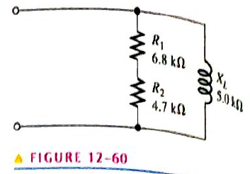
Convert the circuit in Figure 12-60 to an equivalent series form.
Expert Solution & Answer
Want to see the full answer?
Check out a sample textbook solution
Students have asked these similar questions
(a) An AC triangular waveform with peak values of ±2V is used as an
input to a comparator. The outputs of the comparator are
VOH=+5V, VOL=-5V
4
Draw a waveform of the output of the comparator when
an inverting circuit in Figure 5 is used.
(i)
Vi -
20
Vo
20
60
Figure 5
9. Figure 12–62 shows the output voltage of an op-amp in response to a step input. What is the
slew rate?
V out
FIGURE 12–62
+12 V -
15 μ
-12 V-
11. Identify each of the op-amp configurations in Figure 12–63.
What is the half subtractor
Chapter 12 Solutions
Electronics Fundamentals: Circuits, Devices & Applications
Ch. 12 - In an ac circuit where R=XL, the phase angle is...Ch. 12 - Prob. 2TFQCh. 12 - In an ac series RL circuit, the current and...Ch. 12 - In an ac parallel RL circuit, the inductive...Ch. 12 - In an ac parallel RL circuit, the voltage across...Ch. 12 - The unit siemens is used to measure both...Ch. 12 - Prob. 7TFQCh. 12 - If the power factor of a circuit is 0.5, the...Ch. 12 - Prob. 9TFQCh. 12 - Prob. 10TFQ
Ch. 12 - In a series RL circuit, the resistor voltage Leads...Ch. 12 - Prob. 2STCh. 12 - Prob. 3STCh. 12 - If the frequency is doubled and the resistance is...Ch. 12 - Prob. 5STCh. 12 - Prob. 6STCh. 12 - Prob. 7STCh. 12 - Prob. 8STCh. 12 - Prob. 9STCh. 12 - Prob. 10STCh. 12 - Prob. 11STCh. 12 - Prob. 12STCh. 12 - If a load is purely inductive and the reactive...Ch. 12 - Prob. 14STCh. 12 - Prob. 15STCh. 12 - Determine the cause for each set of symptoms....Ch. 12 - Determine the cause for each set of symptoms....Ch. 12 - Prob. 3TSCCh. 12 - Prob. 4TSCCh. 12 - Prob. 5TSCCh. 12 - Prob. 1PCh. 12 - Prob. 2PCh. 12 - Find the impedance of each circuit in Figure...Ch. 12 - Determine the impedance and phase angle in each...Ch. 12 - In Figure 12-52, determine the impedance at each...Ch. 12 - Determine the values of R and XL in a series RL...Ch. 12 - If the frequency of the source is increased to 1...Ch. 12 - Determine the voltage across the total resistance...Ch. 12 - Find the current for each circuit of Figure 12-50.Ch. 12 - Calculate the total current in each circuit of...Ch. 12 - Determine for the cicutit in Figure 12-53.Ch. 12 - If the inductance in Figure 12-53 is doubled, does...Ch. 12 - Draw the waveforms for Vs,VRandVL in Figure 12-53....Ch. 12 - For the circuit in Figure 12-54, find VRandVL for...Ch. 12 - For the lag circuit in Figure 12-55, determine the...Ch. 12 - Repeat Problem 15 for the lead circuit in Figure...Ch. 12 - What is the impedance for the circuit in Figure...Ch. 12 - Repeat Problem 17 for the following frequencies:...Ch. 12 - At what frequecy does XL equal R in Figure 12-57?Ch. 12 - Find the total current and each branch current in...Ch. 12 - Determine the following quantities in Figure...Ch. 12 - Convert the circuit in Figure 12-60 to an...Ch. 12 - Determine the voltage across each element in...Ch. 12 - Is the circuit in Figure 12-61 predominantly...Ch. 12 - Find the current in each branch and the total...Ch. 12 - In a certain RL circuit, the true power is 100 mW,...Ch. 12 - Determine the true power and the reactive power in...Ch. 12 - What is the power factor in Figure 12-58?Ch. 12 - Determine Ptrue,Pr,Pa, and PF for the circuit in...Ch. 12 - Plot the response curve for the circuit in Figure...Ch. 12 - Using the same procedure as in Problem 30, plot...Ch. 12 - Draw the voltage phasor diagram for each circuit...Ch. 12 - Prob. 33PCh. 12 - Prob. 34PCh. 12 - Determine the voltage across the inductors in...Ch. 12 - Is the circuit in Figure 12-64 predominantly...Ch. 12 - Find the total current in Figure 12-64.Ch. 12 - Determine the phase shift and attenuation...Ch. 12 - Design an ideal inductive switching circuit that...Ch. 12 - Prob. 44PCh. 12 - Prob. 45PCh. 12 - Prob. 46PCh. 12 - Prob. 47PCh. 12 - Open file P12-48. Determine if there is a fault...Ch. 12 - Prob. 49P
Knowledge Booster


Learn more about
Need a deep-dive on the concept behind this application? Look no further. Learn more about this topic, electrical-engineering and related others by exploring similar questions and additional content below.Similar questions
- When in forward biased, what have you noticed when you change the source voltage from 0V to +20V? When in reverse biased, what have you noticed when changing the source voltage from 0 V to -15V?arrow_forwardConvert –5 - j30 to exponential formarrow_forward14. Determine the closed-loop gain of each amplifier in Figure 12-65 A=150,000 A=100,000 A=200,000 4444 220 k A=185,000 Figure 12-65arrow_forward
- What is the minimum detectable temperature change that the A-to-D converter can resolve?arrow_forwardThe input voltage to chopper circuit with a switching frequency of 100 Hz and TOn time as 2.0 ms is 10 V. The average DC output is: O 4V O 2V O 6V O 8Varrow_forward(a) An AC triangular waveform with peak values of +2V is used as an input to a comparator. The outputs of the comparator are VOH=+5V, VOL=-5V 4 (ii) Draw a waveform of the output of the comparator when an inverting circuit in Figure 6 with an offset of 1V is used. Vi • 40 Vo 1V 4D 60 Figure 6arrow_forward
- 1.Using the simulator of your choice simulate and screenshot the output voltage wave form for each circuit. +50 V R +5 V Vin Vout R- 47 0 3.3 kN Vin V out -50 V -5 V B Aarrow_forwardA) find the current through each parallel branch in Figure below: A RUcin 17:5AL30- 112 H6 0000 60arrow_forwardDetermine the Q-point for following circuit. Also find new Q-point if value of B changes to 150. Vcc=+12V Rc=560ohm Re=100kohms B VCE + VBE E B=100arrow_forward
- Design a Half adder, Full adder, Half Subtractor and Full Subtractor.arrow_forwardQ/ Analyze the circuit using Kirchhoff's law of currents R= 31n R=5-3 lrvl 56 Varrow_forwardDetermine the minimum and maximum output voltages in the following circuit IADI = 50 LA. -35 Vo- LM337 VOUT R 470 R2 10 knarrow_forward
arrow_back_ios
SEE MORE QUESTIONS
arrow_forward_ios
Recommended textbooks for you
 Delmar's Standard Textbook Of ElectricityElectrical EngineeringISBN:9781337900348Author:Stephen L. HermanPublisher:Cengage Learning
Delmar's Standard Textbook Of Electricity
Electrical Engineering
ISBN:9781337900348
Author:Stephen L. Herman
Publisher:Cengage Learning
02 - Sinusoidal AC Voltage Sources in Circuits, Part 1; Author: Math and Science;https://www.youtube.com/watch?v=8zMiIHVMfaw;License: Standard Youtube License