
Electronics Fundamentals: Circuits, Devices & Applications
8th Edition
ISBN: 9780135072950
Author: Thomas L. Floyd, David Buchla
Publisher: Prentice Hall
expand_more
expand_more
format_list_bulleted
Videos
Textbook Question
Chapter 12, Problem 36P
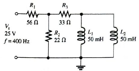
Is the circuit in Figure 12-64 predominantly resistive or predominantly inductive?
Expert Solution & Answer
Want to see the full answer?
Check out a sample textbook solution
Students have asked these similar questions
What is the voltage between nodes A and B in each circuit in Figure 12–73?
Hw MANY MODES, LOOP, MEH IN
THE FIEURE
An RL series circuit is connected to a 240 volt 60 hz line the capacitor has current of 1.25 amperes flowling though it. the Xc of the inductor is 22 ohms. the resistor has a resistance of 16ohms. how much voltage is dropped across the resistor?
Chapter 12 Solutions
Electronics Fundamentals: Circuits, Devices & Applications
Ch. 12 - In an ac circuit where R=XL, the phase angle is...Ch. 12 - Prob. 2TFQCh. 12 - In an ac series RL circuit, the current and...Ch. 12 - In an ac parallel RL circuit, the inductive...Ch. 12 - In an ac parallel RL circuit, the voltage across...Ch. 12 - The unit siemens is used to measure both...Ch. 12 - Prob. 7TFQCh. 12 - If the power factor of a circuit is 0.5, the...Ch. 12 - Prob. 9TFQCh. 12 - Prob. 10TFQ
Ch. 12 - In a series RL circuit, the resistor voltage Leads...Ch. 12 - Prob. 2STCh. 12 - Prob. 3STCh. 12 - If the frequency is doubled and the resistance is...Ch. 12 - Prob. 5STCh. 12 - Prob. 6STCh. 12 - Prob. 7STCh. 12 - Prob. 8STCh. 12 - Prob. 9STCh. 12 - Prob. 10STCh. 12 - Prob. 11STCh. 12 - Prob. 12STCh. 12 - If a load is purely inductive and the reactive...Ch. 12 - Prob. 14STCh. 12 - Prob. 15STCh. 12 - Determine the cause for each set of symptoms....Ch. 12 - Determine the cause for each set of symptoms....Ch. 12 - Prob. 3TSCCh. 12 - Prob. 4TSCCh. 12 - Prob. 5TSCCh. 12 - Prob. 1PCh. 12 - Prob. 2PCh. 12 - Find the impedance of each circuit in Figure...Ch. 12 - Determine the impedance and phase angle in each...Ch. 12 - In Figure 12-52, determine the impedance at each...Ch. 12 - Determine the values of R and XL in a series RL...Ch. 12 - If the frequency of the source is increased to 1...Ch. 12 - Determine the voltage across the total resistance...Ch. 12 - Find the current for each circuit of Figure 12-50.Ch. 12 - Calculate the total current in each circuit of...Ch. 12 - Determine for the cicutit in Figure 12-53.Ch. 12 - If the inductance in Figure 12-53 is doubled, does...Ch. 12 - Draw the waveforms for Vs,VRandVL in Figure 12-53....Ch. 12 - For the circuit in Figure 12-54, find VRandVL for...Ch. 12 - For the lag circuit in Figure 12-55, determine the...Ch. 12 - Repeat Problem 15 for the lead circuit in Figure...Ch. 12 - What is the impedance for the circuit in Figure...Ch. 12 - Repeat Problem 17 for the following frequencies:...Ch. 12 - At what frequecy does XL equal R in Figure 12-57?Ch. 12 - Find the total current and each branch current in...Ch. 12 - Determine the following quantities in Figure...Ch. 12 - Convert the circuit in Figure 12-60 to an...Ch. 12 - Determine the voltage across each element in...Ch. 12 - Is the circuit in Figure 12-61 predominantly...Ch. 12 - Find the current in each branch and the total...Ch. 12 - In a certain RL circuit, the true power is 100 mW,...Ch. 12 - Determine the true power and the reactive power in...Ch. 12 - What is the power factor in Figure 12-58?Ch. 12 - Determine Ptrue,Pr,Pa, and PF for the circuit in...Ch. 12 - Plot the response curve for the circuit in Figure...Ch. 12 - Using the same procedure as in Problem 30, plot...Ch. 12 - Draw the voltage phasor diagram for each circuit...Ch. 12 - Prob. 33PCh. 12 - Prob. 34PCh. 12 - Determine the voltage across the inductors in...Ch. 12 - Is the circuit in Figure 12-64 predominantly...Ch. 12 - Find the total current in Figure 12-64.Ch. 12 - Determine the phase shift and attenuation...Ch. 12 - Design an ideal inductive switching circuit that...Ch. 12 - Prob. 44PCh. 12 - Prob. 45PCh. 12 - Prob. 46PCh. 12 - Prob. 47PCh. 12 - Open file P12-48. Determine if there is a fault...Ch. 12 - Prob. 49P
Knowledge Booster


Learn more about
Need a deep-dive on the concept behind this application? Look no further. Learn more about this topic, electrical-engineering and related others by exploring similar questions and additional content below.Similar questions
- a capacitor and a resistor are connected in parellel to a 120 v 60 hz line the resistor has a resistance of 40 ohms and the capacitor has a capacitance of 132.6 uf what is the total current flow through the circuit. what is the impedence and the power factor and how many degrees out of phase are the current and voltage out phase with eachother.arrow_forwardFor each circuit in Figure 12–70, determine the voltage across each capacitor.arrow_forwardA Resistor and an Inductor of negligible Resistance are connected in series to an AC Supply The PD across the Resistor is 18 V and the PD across the Inductor is 24 V Calculate the Supply Voltage and the Phase Angle between Voltage and Currentarrow_forward
- İf the effective voltage value is 80 volts and the effective current value is 4A in the series RLC circuit in the figure, what is the capacitance of the capacitor?arrow_forwardthe shunt capacitance is a capacitor O a. Between a phase and the ground O b. between phases and a phase to ground c. none of the answers O d. Between phasesarrow_forwardFor the circuit given below, find the current through the capacitor ic R I = 5 A L 30° XC 20 İc = 6.63 L-32.3° A .A O None of the given answers .B O ic = 3.36 32.3° A.C O İc = 3.3 2-45.6° A.D O ic = 3.3 245.6° A .E O ic = 6.53 2-35.3° A .F Oarrow_forward
- This waveform, is the current in Half- .bridge With Purely capacitor Load circuit i Io T/2 T - Io True O False Oarrow_forwarda resistor and and capacitor are connected in parallel to a 277 v 60 hz power source. the resistor has a value of 50 ohms and the capacitor has a value of 40 uf what is the circuit power factor.arrow_forwardin a series Ri. circuit voltage across the resistor is 100 V and the voltage across inductor is 50 V. The power factor of the circuit is O a LII Ob 128 D Oc 0.78 O d. 0.89arrow_forward
- The value of Ai is . . NOTE: When the output is taken from the collector terminal of the transistor as shown in Figure O 85.613 O 78.613 65.613 81.613 89.613 71.613 The value of Zo is .. . ohm. . * 12.897 8.897 6.897 4.897 9.897 O 3.897 The value of Av is .. NOTE: When the output is taken from the collector terminal of the transistor as shown in Figure -17.597 -14.597 -19.597 -21.597 -8.597 -11.597 O O O O O O O O O Oarrow_forwardThe circuit in Figure 24-2 is connected to a 120-V, 60-Hz line. The resistor has a resistance of 36 , the inductor has an inductive reactance of 40 , and the capacitor has a capacitive reactance of 50 . ET120VITZVAPFERIRR36PELILXL40VARsLLECICXC50VARsCCarrow_forwardThe circuit shown in Figure 24-2 has a current of 38 A flowing through the resistor, 22 A flowing through the inductor, and 7 A flowing through the capacitor. What is the total circuit current?arrow_forward
arrow_back_ios
SEE MORE QUESTIONS
arrow_forward_ios
Recommended textbooks for you
 Delmar's Standard Textbook Of ElectricityElectrical EngineeringISBN:9781337900348Author:Stephen L. HermanPublisher:Cengage Learning
Delmar's Standard Textbook Of Electricity
Electrical Engineering
ISBN:9781337900348
Author:Stephen L. Herman
Publisher:Cengage Learning
Inductors Explained - The basics how inductors work working principle; Author: The Engineering Mindset;https://www.youtube.com/watch?v=KSylo01n5FY;License: Standard Youtube License