
Electronics Fundamentals: Circuits, Devices & Applications
8th Edition
ISBN: 9780135072950
Author: Thomas L. Floyd, David Buchla
Publisher: Prentice Hall
expand_more
expand_more
format_list_bulleted
Videos
Textbook Question
Chapter 12, Problem 16P
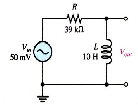
Repeat Problem 15 for the lead circuit in Figure 12-56.
Expert Solution & Answer
Want to see the full answer?
Check out a sample textbook solution
Students have asked these similar questions
9. Figure 12–62 shows the output voltage of an op-amp in response to a step input. What is the
slew rate?
V out
FIGURE 12–62
+12 V -
15 μ
-12 V-
11. Identify each of the op-amp configurations in Figure 12–63.
(a) An AC triangular waveform with peak values of ±2V is used as an
input to a comparator. The outputs of the comparator are
VOH=+5V, VOL=-5V
4
Draw a waveform of the output of the comparator when
an inverting circuit in Figure 5 is used.
(i)
Vi -
20
Vo
20
60
Figure 5
the following waveform is the
inductor current of the buck converter,
the ripple current is equal to
Q7) the following waveform is the inductor current of the buck converter, the
ripple current is equal to
Inductor current
35
30-
25-
20-
Lead voltage
Oa) 14A
b) 15A
c) 16A
d) 17A
Chapter 12 Solutions
Electronics Fundamentals: Circuits, Devices & Applications
Ch. 12 - In an ac circuit where R=XL, the phase angle is...Ch. 12 - Prob. 2TFQCh. 12 - In an ac series RL circuit, the current and...Ch. 12 - In an ac parallel RL circuit, the inductive...Ch. 12 - In an ac parallel RL circuit, the voltage across...Ch. 12 - The unit siemens is used to measure both...Ch. 12 - Prob. 7TFQCh. 12 - If the power factor of a circuit is 0.5, the...Ch. 12 - Prob. 9TFQCh. 12 - Prob. 10TFQ
Ch. 12 - In a series RL circuit, the resistor voltage Leads...Ch. 12 - Prob. 2STCh. 12 - Prob. 3STCh. 12 - If the frequency is doubled and the resistance is...Ch. 12 - Prob. 5STCh. 12 - Prob. 6STCh. 12 - Prob. 7STCh. 12 - Prob. 8STCh. 12 - Prob. 9STCh. 12 - Prob. 10STCh. 12 - Prob. 11STCh. 12 - Prob. 12STCh. 12 - If a load is purely inductive and the reactive...Ch. 12 - Prob. 14STCh. 12 - Prob. 15STCh. 12 - Determine the cause for each set of symptoms....Ch. 12 - Determine the cause for each set of symptoms....Ch. 12 - Prob. 3TSCCh. 12 - Prob. 4TSCCh. 12 - Prob. 5TSCCh. 12 - Prob. 1PCh. 12 - Prob. 2PCh. 12 - Find the impedance of each circuit in Figure...Ch. 12 - Determine the impedance and phase angle in each...Ch. 12 - In Figure 12-52, determine the impedance at each...Ch. 12 - Determine the values of R and XL in a series RL...Ch. 12 - If the frequency of the source is increased to 1...Ch. 12 - Determine the voltage across the total resistance...Ch. 12 - Find the current for each circuit of Figure 12-50.Ch. 12 - Calculate the total current in each circuit of...Ch. 12 - Determine for the cicutit in Figure 12-53.Ch. 12 - If the inductance in Figure 12-53 is doubled, does...Ch. 12 - Draw the waveforms for Vs,VRandVL in Figure 12-53....Ch. 12 - For the circuit in Figure 12-54, find VRandVL for...Ch. 12 - For the lag circuit in Figure 12-55, determine the...Ch. 12 - Repeat Problem 15 for the lead circuit in Figure...Ch. 12 - What is the impedance for the circuit in Figure...Ch. 12 - Repeat Problem 17 for the following frequencies:...Ch. 12 - At what frequecy does XL equal R in Figure 12-57?Ch. 12 - Find the total current and each branch current in...Ch. 12 - Determine the following quantities in Figure...Ch. 12 - Convert the circuit in Figure 12-60 to an...Ch. 12 - Determine the voltage across each element in...Ch. 12 - Is the circuit in Figure 12-61 predominantly...Ch. 12 - Find the current in each branch and the total...Ch. 12 - In a certain RL circuit, the true power is 100 mW,...Ch. 12 - Determine the true power and the reactive power in...Ch. 12 - What is the power factor in Figure 12-58?Ch. 12 - Determine Ptrue,Pr,Pa, and PF for the circuit in...Ch. 12 - Plot the response curve for the circuit in Figure...Ch. 12 - Using the same procedure as in Problem 30, plot...Ch. 12 - Draw the voltage phasor diagram for each circuit...Ch. 12 - Prob. 33PCh. 12 - Prob. 34PCh. 12 - Determine the voltage across the inductors in...Ch. 12 - Is the circuit in Figure 12-64 predominantly...Ch. 12 - Find the total current in Figure 12-64.Ch. 12 - Determine the phase shift and attenuation...Ch. 12 - Design an ideal inductive switching circuit that...Ch. 12 - Prob. 44PCh. 12 - Prob. 45PCh. 12 - Prob. 46PCh. 12 - Prob. 47PCh. 12 - Open file P12-48. Determine if there is a fault...Ch. 12 - Prob. 49P
Knowledge Booster


Learn more about
Need a deep-dive on the concept behind this application? Look no further. Learn more about this topic, electrical-engineering and related others by exploring similar questions and additional content below.Similar questions
- 14. Determine the closed-loop gain of each amplifier in Figure 12-65 A=150,000 A=100,000 A=200,000 4444 220 k A=185,000 Figure 12-65arrow_forward17. If a signal voltage of 10 mV rms is applied to each amplifier in Figure 12–66, what are the out- put voltages and what is their phase relationship with inputs? 1.0 MO R 47 karrow_forward(a) An AC triangular waveform with peak values of +2V is used as an input to a comparator. The outputs of the comparator are VOH=+5V, VOL=-5V 4 (ii) Draw a waveform of the output of the comparator when an inverting circuit in Figure 6 with an offset of 1V is used. Vi • 40 Vo 1V 4D 60 Figure 6arrow_forward
- The input voltage to chopper circuit with a switching frequency of 100 Hz and TOn time as 2.0 ms is 10 V. The average DC output is: O 4V O 2V O 6V O 8Varrow_forwardDetermine Rc, RE, RB, VCE0, & VB 12V Ic = 2 mA Ro RB 7.6 V B = 80 B VCE E 2.4 V REarrow_forwardmake sure to show the last step summing the impedence in parallel thank you.arrow_forward
- The equivalent inductance seen at terminal AB in figure isarrow_forwardQ6 B only please thank youarrow_forwardUsually, a multistage amplifier connection can be used to increase the overall small-signal voltage gain and to provideoutput impedance. A very high B) zero (c) infinite D) very lowarrow_forward
arrow_back_ios
SEE MORE QUESTIONS
arrow_forward_ios
Recommended textbooks for you
 Delmar's Standard Textbook Of ElectricityElectrical EngineeringISBN:9781337900348Author:Stephen L. HermanPublisher:Cengage Learning
Delmar's Standard Textbook Of Electricity
Electrical Engineering
ISBN:9781337900348
Author:Stephen L. Herman
Publisher:Cengage Learning
Resonance Circuits: LC Inductor-Capacitor Resonating Circuits; Author: Physics Videos by Eugene Khutoryansky;https://www.youtube.com/watch?v=Mq-PF1vo9QA;License: Standard YouTube License, CC-BY