
Electronics Fundamentals: Circuits, Devices & Applications
8th Edition
ISBN: 9780135072950
Author: Thomas L. Floyd, David Buchla
Publisher: Prentice Hall
expand_more
expand_more
format_list_bulleted
Videos
Textbook Question
Chapter 12, Problem 19P
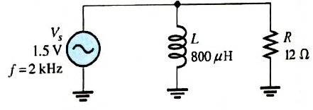
At what frequecy does
Expert Solution & Answer
Want to see the full answer?
Check out a sample textbook solution
Students have asked these similar questions
9. Figure 12–62 shows the output voltage of an op-amp in response to a step input. What is the
slew rate?
V out
FIGURE 12–62
+12 V -
15 μ
-12 V-
11. Identify each of the op-amp configurations in Figure 12–63.
t Caleule lo siguiente si VgD = 750 C6S(17OT +65)V
(Utlice fasores).
950
Ri 52Sr
L=0.SH
Va
CF409 nF
C= 976 nP
Solve the approximate value of Rg of Figure 44.
VCC
12V
Ⓒ468 A
356 A
Ⓒ333 AN
340 KS2
RB
RC
Q1
Beta = 80
RE
1.2kQ
Figure 44
V=7.6V
V = 2.4V
Chapter 12 Solutions
Electronics Fundamentals: Circuits, Devices & Applications
Ch. 12 - In an ac circuit where R=XL, the phase angle is...Ch. 12 - Prob. 2TFQCh. 12 - In an ac series RL circuit, the current and...Ch. 12 - In an ac parallel RL circuit, the inductive...Ch. 12 - In an ac parallel RL circuit, the voltage across...Ch. 12 - The unit siemens is used to measure both...Ch. 12 - Prob. 7TFQCh. 12 - If the power factor of a circuit is 0.5, the...Ch. 12 - Prob. 9TFQCh. 12 - Prob. 10TFQ
Ch. 12 - In a series RL circuit, the resistor voltage Leads...Ch. 12 - Prob. 2STCh. 12 - Prob. 3STCh. 12 - If the frequency is doubled and the resistance is...Ch. 12 - Prob. 5STCh. 12 - Prob. 6STCh. 12 - Prob. 7STCh. 12 - Prob. 8STCh. 12 - Prob. 9STCh. 12 - Prob. 10STCh. 12 - Prob. 11STCh. 12 - Prob. 12STCh. 12 - If a load is purely inductive and the reactive...Ch. 12 - Prob. 14STCh. 12 - Prob. 15STCh. 12 - Determine the cause for each set of symptoms....Ch. 12 - Determine the cause for each set of symptoms....Ch. 12 - Prob. 3TSCCh. 12 - Prob. 4TSCCh. 12 - Prob. 5TSCCh. 12 - Prob. 1PCh. 12 - Prob. 2PCh. 12 - Find the impedance of each circuit in Figure...Ch. 12 - Determine the impedance and phase angle in each...Ch. 12 - In Figure 12-52, determine the impedance at each...Ch. 12 - Determine the values of R and XL in a series RL...Ch. 12 - If the frequency of the source is increased to 1...Ch. 12 - Determine the voltage across the total resistance...Ch. 12 - Find the current for each circuit of Figure 12-50.Ch. 12 - Calculate the total current in each circuit of...Ch. 12 - Determine for the cicutit in Figure 12-53.Ch. 12 - If the inductance in Figure 12-53 is doubled, does...Ch. 12 - Draw the waveforms for Vs,VRandVL in Figure 12-53....Ch. 12 - For the circuit in Figure 12-54, find VRandVL for...Ch. 12 - For the lag circuit in Figure 12-55, determine the...Ch. 12 - Repeat Problem 15 for the lead circuit in Figure...Ch. 12 - What is the impedance for the circuit in Figure...Ch. 12 - Repeat Problem 17 for the following frequencies:...Ch. 12 - At what frequecy does XL equal R in Figure 12-57?Ch. 12 - Find the total current and each branch current in...Ch. 12 - Determine the following quantities in Figure...Ch. 12 - Convert the circuit in Figure 12-60 to an...Ch. 12 - Determine the voltage across each element in...Ch. 12 - Is the circuit in Figure 12-61 predominantly...Ch. 12 - Find the current in each branch and the total...Ch. 12 - In a certain RL circuit, the true power is 100 mW,...Ch. 12 - Determine the true power and the reactive power in...Ch. 12 - What is the power factor in Figure 12-58?Ch. 12 - Determine Ptrue,Pr,Pa, and PF for the circuit in...Ch. 12 - Plot the response curve for the circuit in Figure...Ch. 12 - Using the same procedure as in Problem 30, plot...Ch. 12 - Draw the voltage phasor diagram for each circuit...Ch. 12 - Prob. 33PCh. 12 - Prob. 34PCh. 12 - Determine the voltage across the inductors in...Ch. 12 - Is the circuit in Figure 12-64 predominantly...Ch. 12 - Find the total current in Figure 12-64.Ch. 12 - Determine the phase shift and attenuation...Ch. 12 - Design an ideal inductive switching circuit that...Ch. 12 - Prob. 44PCh. 12 - Prob. 45PCh. 12 - Prob. 46PCh. 12 - Prob. 47PCh. 12 - Open file P12-48. Determine if there is a fault...Ch. 12 - Prob. 49P
Knowledge Booster


Learn more about
Need a deep-dive on the concept behind this application? Look no further. Learn more about this topic, electrical-engineering and related others by exploring similar questions and additional content below.Similar questions
- Q/ Analyze the circuit using Kirchhoff's law of currents R= 31n R=5-3 lrvl 56 Varrow_forward18 Determine Ic in the given circuit if VBB = 5V, VCC = 15V, RB = 10k and RC = 200 Q. Assume 3 = 100 * Rc RB www +V₂ BB til Hi =+Vccarrow_forwardA) find the current through each parallel branch in Figure below: A RUcin 17:5AL30- 112 H6 0000 60arrow_forward
- 4 – 2j. 2j + 2 +j | Simplify 1-j O -0.1 + 0.2 j O 0.3 - 0.4j O 0.4 + 0.5 j 0.8 + 0.4j 0.2 + 0.1 j O 0.1 + 0.3j O 0.2 - 0.6 j O -0.6 - 0.7 jarrow_forwardDetermine the curreut that Hlows the chcut iu the fitere below 52 12 a-24 C-Q5A d.0.2Aarrow_forwardThe value of Ai is . . NOTE: When the output is taken from the collector terminal of the transistor as shown in Figure O 85.613 O 78.613 65.613 81.613 89.613 71.613 The value of Zo is .. . ohm. . * 12.897 8.897 6.897 4.897 9.897 O 3.897 The value of Av is .. NOTE: When the output is taken from the collector terminal of the transistor as shown in Figure -17.597 -14.597 -19.597 -21.597 -8.597 -11.597 O O O O O O O O O Oarrow_forward
- Plot the output voltage of the following circuit, explain your procedure step by step R1 01 1002 V1 D1 7Vrms |60HZ A@2v refarrow_forwardGiven the circuit in Figure 16-5, what is the RMS current through the inductor? XL = 300 Ω 600 Vrms O 2.00 A O 3 A Vs 4.69 MA O 5 A Figure 165 R = 600 Ωarrow_forwardSimplify BC + B(A+B) + B(A+C) Answer O B+AC O A O A+BC O Barrow_forward
arrow_back_ios
SEE MORE QUESTIONS
arrow_forward_ios
Recommended textbooks for you
 Delmar's Standard Textbook Of ElectricityElectrical EngineeringISBN:9781337900348Author:Stephen L. HermanPublisher:Cengage Learning
Delmar's Standard Textbook Of Electricity
Electrical Engineering
ISBN:9781337900348
Author:Stephen L. Herman
Publisher:Cengage Learning
02 - Sinusoidal AC Voltage Sources in Circuits, Part 1; Author: Math and Science;https://www.youtube.com/watch?v=8zMiIHVMfaw;License: Standard Youtube License