
Electronics Fundamentals: Circuits, Devices & Applications
8th Edition
ISBN: 9780135072950
Author: Thomas L. Floyd, David Buchla
Publisher: Prentice Hall
expand_more
expand_more
format_list_bulleted
Concept explainers
Videos
Textbook Question
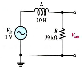
Chapter 12, Problem 15P
For the lag circuit in Figure 12-55, determine the phase lag of the output voltage with respect to the input for the following frequencies:
Expert Solution & Answer
Want to see the full answer?
Check out a sample textbook solution
Students have asked these similar questions
7.2
At t = 0, the switch in the circuit shown moves
instantaneously from position a to position b.
a) Calculate v, for t≥ 0.
b) What percentage of the initial energy stored
in the inductor is eventually dissipated in
the 4
resistor?
6Ω
a
w
+
10 0.32 H3 403
6.4 A
=0
b
Answer: (a) -8e-10 V, t = 0;
(b) 80%.
At t = 0, the switch closes. Find the IL(t) and VL(t) for t≥ 0 in t and s domain.
Can you help me?
1)
(+.
24V
ง
Anahtar t=0 anında kapatılıyor.
to icin TL(t) ve
bulunuz.
J
3√√√2
ww
مفروم
+
t=0
$6.5 5H VLCH) 2.2
Vilt)
"For the network in the figure, determine RE and RB if A₁
Zb = BRE."
=
-10 and re
=
3.8. Assume that
Chapter 12 Solutions
Electronics Fundamentals: Circuits, Devices & Applications
Ch. 12 - In an ac circuit where R=XL, the phase angle is...Ch. 12 - Prob. 2TFQCh. 12 - In an ac series RL circuit, the current and...Ch. 12 - In an ac parallel RL circuit, the inductive...Ch. 12 - In an ac parallel RL circuit, the voltage across...Ch. 12 - The unit siemens is used to measure both...Ch. 12 - Prob. 7TFQCh. 12 - If the power factor of a circuit is 0.5, the...Ch. 12 - Prob. 9TFQCh. 12 - Prob. 10TFQ
Ch. 12 - In a series RL circuit, the resistor voltage Leads...Ch. 12 - Prob. 2STCh. 12 - Prob. 3STCh. 12 - If the frequency is doubled and the resistance is...Ch. 12 - Prob. 5STCh. 12 - Prob. 6STCh. 12 - Prob. 7STCh. 12 - Prob. 8STCh. 12 - Prob. 9STCh. 12 - Prob. 10STCh. 12 - Prob. 11STCh. 12 - Prob. 12STCh. 12 - If a load is purely inductive and the reactive...Ch. 12 - Prob. 14STCh. 12 - Prob. 15STCh. 12 - Determine the cause for each set of symptoms....Ch. 12 - Determine the cause for each set of symptoms....Ch. 12 - Prob. 3TSCCh. 12 - Prob. 4TSCCh. 12 - Prob. 5TSCCh. 12 - Prob. 1PCh. 12 - Prob. 2PCh. 12 - Find the impedance of each circuit in Figure...Ch. 12 - Determine the impedance and phase angle in each...Ch. 12 - In Figure 12-52, determine the impedance at each...Ch. 12 - Determine the values of R and XL in a series RL...Ch. 12 - If the frequency of the source is increased to 1...Ch. 12 - Determine the voltage across the total resistance...Ch. 12 - Find the current for each circuit of Figure 12-50.Ch. 12 - Calculate the total current in each circuit of...Ch. 12 - Determine for the cicutit in Figure 12-53.Ch. 12 - If the inductance in Figure 12-53 is doubled, does...Ch. 12 - Draw the waveforms for Vs,VRandVL in Figure 12-53....Ch. 12 - For the circuit in Figure 12-54, find VRandVL for...Ch. 12 - For the lag circuit in Figure 12-55, determine the...Ch. 12 - Repeat Problem 15 for the lead circuit in Figure...Ch. 12 - What is the impedance for the circuit in Figure...Ch. 12 - Repeat Problem 17 for the following frequencies:...Ch. 12 - At what frequecy does XL equal R in Figure 12-57?Ch. 12 - Find the total current and each branch current in...Ch. 12 - Determine the following quantities in Figure...Ch. 12 - Convert the circuit in Figure 12-60 to an...Ch. 12 - Determine the voltage across each element in...Ch. 12 - Is the circuit in Figure 12-61 predominantly...Ch. 12 - Find the current in each branch and the total...Ch. 12 - In a certain RL circuit, the true power is 100 mW,...Ch. 12 - Determine the true power and the reactive power in...Ch. 12 - What is the power factor in Figure 12-58?Ch. 12 - Determine Ptrue,Pr,Pa, and PF for the circuit in...Ch. 12 - Plot the response curve for the circuit in Figure...Ch. 12 - Using the same procedure as in Problem 30, plot...Ch. 12 - Draw the voltage phasor diagram for each circuit...Ch. 12 - Prob. 33PCh. 12 - Prob. 34PCh. 12 - Determine the voltage across the inductors in...Ch. 12 - Is the circuit in Figure 12-64 predominantly...Ch. 12 - Find the total current in Figure 12-64.Ch. 12 - Determine the phase shift and attenuation...Ch. 12 - Design an ideal inductive switching circuit that...Ch. 12 - Prob. 44PCh. 12 - Prob. 45PCh. 12 - Prob. 46PCh. 12 - Prob. 47PCh. 12 - Open file P12-48. Determine if there is a fault...Ch. 12 - Prob. 49P
Knowledge Booster


Learn more about
Need a deep-dive on the concept behind this application? Look no further. Learn more about this topic, electrical-engineering and related others by exploring similar questions and additional content below.Similar questions
- 2.a. Simplify and determine Zk+ for: 2.x. 60 [Hz] ⚫ 2.y. 180 [Hz] a.x. 60[Hz] a.y. 180 [Hz] Joo (127 2[H] w 240 [√]arrow_forwardP3. Given the following network, determine: ⚫ 3.a. Equivalent Y ⚫ 3.b. Equivalent A 2 R[2] 10 8 b 20 30 5arrow_forward[Electrical Circuits] P1. Using the mesh current method, calculate the magnitude and direction of: 1.a. I and I (mesh currents) 1.b. I10 (test current in R10 = 1082) 1.c. (Calculate the magnitude and signs of V10) 6[A] 12 [√] بي 10 38 20 4A] Iw -800arrow_forward
- Need handwritten solution do not use chatgptarrow_forward[07/01, 16:59] C P: Question: Calculate the following for 100Hz and 500Hz (express all answers in phasor form). Show all work. A) Xc and ZTB) VR1 and VC1 C) IT Handwritten Solution Pleasearrow_forward1. Sketch the root loci of a system with the following characteristic equation: s²+2s+2+K(s+2)=0 2. Sketch the root loci for the following loop transfer function: KG(s)H(s)=- K(s+1) s(s+2)(s²+2s+4)arrow_forward
- 3. For the unity feedback system with forward path transfer function, G(s), below: G(s)= K(s² +8) (s+4)(s+5) Sketch the root locus and show the breakaway/break-in point(s) and jo-axis crossing. Determine the angle of arrival and K value at the breakaway/break- in point(s). Give your comment the system is stable or unstable.arrow_forwardFind the step response of each of the transfer functions shown in Eqs. (4.62) through (4.64) and compare them. [Shown in the image]Book: Norman S. Nise - Control Systems Engineering, 6th EditionTopic: Chapter-4: Time Response, Example 4.8Solve the math with proper explanation. Please don't give AI response. Asking for a expert verified answer.arrow_forward2. With respect to the circuit shown in Figure 2 below V2 -R1 R2 R4 w R3 R5 Figure 2: DC Circuit 2 a. Using Ohm's and Kirchhoff's laws calculate the current flowing through R3 and so determine wattage rating of R3. b. Verify your results with simulations. Note: you must use the values for the components in Table 2. Table 2 V2 (Volts) R1 (KQ) R2 (KQ) R3 (KQ) R4 (KQ) R5 (KQ) 9 3.3 5 10 6 1 3.3arrow_forward
arrow_back_ios
SEE MORE QUESTIONS
arrow_forward_ios
Recommended textbooks for you
 Introductory Circuit Analysis (13th Edition)Electrical EngineeringISBN:9780133923605Author:Robert L. BoylestadPublisher:PEARSON
 Delmar's Standard Textbook Of ElectricityElectrical EngineeringISBN:9781337900348Author:Stephen L. HermanPublisher:Cengage Learning
 Programmable Logic ControllersElectrical EngineeringISBN:9780073373843Author:Frank D. PetruzellaPublisher:McGraw-Hill Education
 Fundamentals of Electric CircuitsElectrical EngineeringISBN:9780078028229Author:Charles K Alexander, Matthew SadikuPublisher:McGraw-Hill Education
 Electric Circuits. (11th Edition)Electrical EngineeringISBN:9780134746968Author:James W. Nilsson, Susan RiedelPublisher:PEARSON
 Engineering ElectromagneticsElectrical EngineeringISBN:9780078028151Author:Hayt, William H. (william Hart), Jr, BUCK, John A.Publisher:Mcgraw-hill Education,
Introductory Circuit Analysis (13th Edition)
Electrical Engineering
ISBN:9780133923605
Author:Robert L. Boylestad
Publisher:PEARSON
Delmar's Standard Textbook Of Electricity
Electrical Engineering
ISBN:9781337900348
Author:Stephen L. Herman
Publisher:Cengage Learning
Programmable Logic Controllers
Electrical Engineering
ISBN:9780073373843
Author:Frank D. Petruzella
Publisher:McGraw-Hill Education
Fundamentals of Electric Circuits
Electrical Engineering
ISBN:9780078028229
Author:Charles K Alexander, Matthew Sadiku
Publisher:McGraw-Hill Education
Electric Circuits. (11th Edition)
Electrical Engineering
ISBN:9780134746968
Author:James W. Nilsson, Susan Riedel
Publisher:PEARSON
Engineering Electromagnetics
Electrical Engineering
ISBN:9780078028151
Author:Hayt, William H. (william Hart), Jr, BUCK, John A.
Publisher:Mcgraw-hill Education,
Z Parameters - Impedance Parameters; Author: Electrical Engineering Authority;https://www.youtube.com/watch?v=qoD4AoNmySA;License: Standard Youtube License