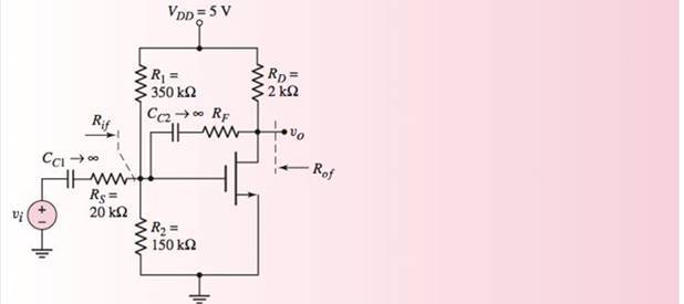
Consider the circuit in Figure 12.39, with transistor parameters V T N = 0.8 V , K n = 1.5 mA / V 2 , and λ = 0. ( a ) ( i ) Find the open-loop gain for R F = ∞ . (ii) Find the closed-loop gain for R F = 47 k Ω . (b) Repeat part (a) if the conductance parameter decreases by 15 percent to K n = 1.275 mA / V 2 . What is the percent change in the magnitude of each gain factor? (Ans. (a) (i) A v = − 3.528 (ii) A v f = − 1.204 (b) (i) A v = − 3.0 , − 15 % change; (ii) A v f = − 1.107 , − 8.06 % change) Figure 12.39 Circuit for Exercises Ex 12.13 and Ex 12.14
Consider the circuit in Figure 12.39, with transistor parameters V T N = 0.8 V , K n = 1.5 mA / V 2 , and λ = 0. ( a ) ( i ) Find the open-loop gain for R F = ∞ . (ii) Find the closed-loop gain for R F = 47 k Ω . (b) Repeat part (a) if the conductance parameter decreases by 15 percent to K n = 1.275 mA / V 2 . What is the percent change in the magnitude of each gain factor? (Ans. (a) (i) A v = − 3.528 (ii) A v f = − 1.204 (b) (i) A v = − 3.0 , − 15 % change; (ii) A v f = − 1.107 , − 8.06 % change) Figure 12.39 Circuit for Exercises Ex 12.13 and Ex 12.14
Solution Summary: The author compares the value of the open loop gain and the closed loop voltage gain. The small signal equivalent circuit is shown in Figure 1.
Consider the circuit in Figure 12.39, with transistor parameters
V
T
N
=
0.8
V
,
K
n
=
1.5
mA
/
V
2
,
and
λ
=
0.
(
a
)
(
i
)
Find the open-loop gain for
R
F
=
∞
.
(ii) Find the closed-loop gain for
R
F
=
47
k
Ω
.
(b) Repeat part (a) if the conductance parameter decreases by 15 percent to
K
n
=
1.275
mA
/
V
2
.
What is the percent change in the magnitude of each gain factor? (Ans. (a) (i)
A
v
=
−
3.528
(ii)
A
v
f
=
−
1.204
(b) (i)
A
v
=
−
3.0
,
−
15
%
change; (ii)
A
v
f
=
−
1.107
,
−
8.06
%
change)
Figure 12.39 Circuit for Exercises Ex 12.13 and Ex 12.14
Design a collector-feedback circuit using with Vcc = 5 V, Ic
= 10 mA, and VCE = 1.5 V.
For the 2 circuits shown above, βnpn = 100, βpnp = 50, VDO = 0.7 V, R2 = 150 kΩ, and RB = 12 kΩ Using the ac small-scale signal analysis, determine for each circuit:
a) The voltage gain (Av = vout/vin)
b) The input resistance (Rin)
c) The output resistance (Rout)
Adiff-amp is biased with a constant-current source lo- 0.25mA that has an output resistance of R. - 8MO. The bipolar transistor parameters are B=100, VT = 0.025 V and VA -.
Determine the common-mode input resistance.
O a. Ricm = 538 MA
O b.Ricm- 308 MO
OC Ricm = 808 MO
Od Ricm = 704 MQ
Need a deep-dive on the concept behind this application? Look no further. Learn more about this topic, electrical-engineering and related others by exploring similar questions and additional content below.


 Introductory Circuit Analysis (13th Edition)Electrical EngineeringISBN:9780133923605Author:Robert L. BoylestadPublisher:PEARSON
 Delmar's Standard Textbook Of ElectricityElectrical EngineeringISBN:9781337900348Author:Stephen L. HermanPublisher:Cengage Learning
 Programmable Logic ControllersElectrical EngineeringISBN:9780073373843Author:Frank D. PetruzellaPublisher:McGraw-Hill Education
 Fundamentals of Electric CircuitsElectrical EngineeringISBN:9780078028229Author:Charles K Alexander, Matthew SadikuPublisher:McGraw-Hill Education
 Electric Circuits. (11th Edition)Electrical EngineeringISBN:9780134746968Author:James W. Nilsson, Susan RiedelPublisher:PEARSON
 Engineering ElectromagneticsElectrical EngineeringISBN:9780078028151Author:Hayt, William H. (william Hart), Jr, BUCK, John A.Publisher:Mcgraw-hill Education,