
Microelectronics: Circuit Analysis and Design
4th Edition
ISBN: 9780073380643
Author: Donald A. Neamen
Publisher: McGraw-Hill Companies, The
expand_more
expand_more
format_list_bulleted
Videos
Textbook Question
Chapter 12, Problem 12.23P
An op-amp circuit is shown in Figure
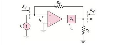
Figure P12.22
Expert Solution & Answer
Want to see the full answer?
Check out a sample textbook solution
Students have asked these similar questions
An op-amp with open-loop parameters OFAOL = 2 x 10⁵ and fPD = 5 Hz is connected in a
noninverting amplifier configuration with a low- frequency closed-loop gain of ACLO = 30. An
input voltage signal of v = 100sin(27ft) P V is applied. (a) What is the closed-loop bandwidth?
P12.6. For each of the circuits shown in Figure P12.6, assume that the op
is ideal and find the value of vo. Each of the circuits has negative
feedback, so the summing-point constraint applies.
amp
1 kN
3 ΚΩ
2 mA
2 mA
5 V 3
(a)
(b)
()3mA
15 kQ
1 V
3 kN
(d)
Vo
1 kQ
5 V
4 V
1 kQ
2 V
(c)
(e)
10||
Find the expression for the open loop gain Rm (=Output voltage/Input current). Get the expression for Ro,cl (closed loop output resistance).
Chapter 12 Solutions
Microelectronics: Circuit Analysis and Design
Ch. 12 - (a) The open-loop gain of an amplifier is A=5104...Ch. 12 - (a) Consider a general feedback system with...Ch. 12 - (a) A feedback amplifier has an open-loop...Ch. 12 - (a) Consider the circuit shown in Figure...Ch. 12 - (a) The closed-loop gain of a feedback amplifier...Ch. 12 - The gain factors in a feedback system are A=5105...Ch. 12 - Prob. 12.3TYUCh. 12 - An ideal series-shunt feedback amplifier is shown...Ch. 12 - Consider the ideal shunt-series feedback amplifier...Ch. 12 - An ideal series-series feedback amplifier is shown...
Ch. 12 - Prob. 12.5TYUCh. 12 - Consider the noninverting op-amp circuit shown in...Ch. 12 - Design a feedback voltage amplifier to provide a...Ch. 12 - Prob. 12.6TYUCh. 12 - (a) Assume the transistor in the source-follower...Ch. 12 - Consider the common-base circuit in Figure...Ch. 12 - Design a feedback current amplifier to provide a...Ch. 12 - Prob. 12.8TYUCh. 12 - Prob. 12.9TYUCh. 12 - For the circuit in Figure 12.31, the transistor...Ch. 12 - Design a transconductance feedback amplifier with...Ch. 12 - Prob. 12.10TYUCh. 12 - Consider the circuit in Figure 12.39, with...Ch. 12 - Consider the BJT feedback circuit in Figure...Ch. 12 - Prob. 12.12TYUCh. 12 - Consider the circuit in Figure...Ch. 12 - Prob. 12.16EPCh. 12 - Prob. 12.17EPCh. 12 - Consider the circuit in Figure 12.44(a) with...Ch. 12 - Consider the circuit in Figure 12.16 with the...Ch. 12 - Prob. 12.18EPCh. 12 - Consider the loop gain function T(f)=(3000)(1+jf...Ch. 12 - Consider the loop gain function given in Exercise...Ch. 12 - Prob. 12.16TYUCh. 12 - Prob. 12.17TYUCh. 12 - Prob. 12.20EPCh. 12 - Prob. 12.21EPCh. 12 - Prob. 12.22EPCh. 12 - What are the two general types of feedback and...Ch. 12 - Prob. 2RQCh. 12 - Prob. 3RQCh. 12 - Prob. 4RQCh. 12 - Prob. 5RQCh. 12 - Prob. 6RQCh. 12 - Describe the series and shunt output connections...Ch. 12 - Describe the effect of a series or shunt input...Ch. 12 - Describe the effect of a series or shunt output...Ch. 12 - Consider a noninverting op-amp circuit. Describe...Ch. 12 - Prob. 11RQCh. 12 - What is the Nyquist stability criterion for a...Ch. 12 - Using Bode plots, describe the conditions of...Ch. 12 - Prob. 14RQCh. 12 - Prob. 15RQCh. 12 - Prob. 16RQCh. 12 - Prob. 17RQCh. 12 - (a) A negative-feedback amplifier has a...Ch. 12 - Prob. 12.2PCh. 12 - The ideal feedback transfer function is given by...Ch. 12 - Prob. 12.4PCh. 12 - Consider the feedback system shown in Figure 12.1...Ch. 12 - The open-loop gain of an amplifier is A=5104. If...Ch. 12 - Two feedback configurations are shown in Figures...Ch. 12 - Three voltage amplifiers are in cascade as shown...Ch. 12 - (a) The open-loop low-frequency voltage gain of an...Ch. 12 - (a) Determine the closed-loop bandwidth of a...Ch. 12 - (a) An inverting amplifier uses an op-amp with an...Ch. 12 - The basic amplifier in a feedback configuration...Ch. 12 - Consider the two feedback networks shown in...Ch. 12 - Prob. 12.14PCh. 12 - Two feedback configurations are shown in Figures...Ch. 12 - Prob. 12.16PCh. 12 - The parameters of the ideal series-shunt circuit...Ch. 12 - For the noninverting op-amp circuit in Figure...Ch. 12 - Consider the noninverting op-amp circuit in Figure...Ch. 12 - The circuit parameters of the ideal shunt-series...Ch. 12 - Consider the ideal shunt-series amplifier shown in...Ch. 12 - Consider the op-amp circuit in Figure P12.22. The...Ch. 12 - An op-amp circuit is shown in Figure P12.22. Its...Ch. 12 - Prob. 12.24PCh. 12 - Prob. 12.25PCh. 12 - Consider the circuit in Figure P12.26. The input...Ch. 12 - The circuit shown in Figure P12.26 has the same...Ch. 12 - The circuit parameters of the ideal shunt-shunt...Ch. 12 - Prob. 12.29PCh. 12 - Consider the current-to-voltage converter circuit...Ch. 12 - Prob. 12.31PCh. 12 - Determine the type of feedback configuration that...Ch. 12 - Prob. 12.33PCh. 12 - A compound transconductance amplifier is to be...Ch. 12 - The parameters of the op-amp in the circuit shown...Ch. 12 - Prob. 12.36PCh. 12 - Consider the series-shunt feedback circuit in...Ch. 12 - The circuit shown in Figure P12.38 is an ac...Ch. 12 - Prob. 12.39PCh. 12 - Prob. 12.40PCh. 12 - Prob. 12.41PCh. 12 - Prob. 12.42PCh. 12 - Prob. D12.43PCh. 12 - Prob. D12.44PCh. 12 - An op-amp current gain amplifier is shown in...Ch. 12 - Prob. 12.46PCh. 12 - Prob. 12.47PCh. 12 - Prob. 12.48PCh. 12 - The circuit in Figure P 12.49 has transistor...Ch. 12 - (a) Using the small-signal equivalent circuit in...Ch. 12 - The circuit in Figure P12.51 is an example of a...Ch. 12 - Prob. 12.52PCh. 12 - For the transistors in the circuit in Figure P...Ch. 12 - Consider the transconductance amplifier shown in...Ch. 12 - Consider the transconductance feedback amplifier...Ch. 12 - Prob. 12.57PCh. 12 - Prob. D12.58PCh. 12 - Prob. 12.59PCh. 12 - Prob. D12.60PCh. 12 - Prob. 12.61PCh. 12 - The transistor parameters for the circuit shown in...Ch. 12 - Prob. 12.63PCh. 12 - For the circuit in Figure P 12.64, the transistor...Ch. 12 - Prob. 12.65PCh. 12 - Prob. 12.66PCh. 12 - Design a feedback transresistance amplifier using...Ch. 12 - Prob. 12.68PCh. 12 - Prob. 12.69PCh. 12 - Prob. 12.70PCh. 12 - The transistor parameters for the circuit shown in...Ch. 12 - Prob. 12.72PCh. 12 - The open-loop voltage gain of an amplifier is...Ch. 12 - A loop gain function is given by T(f)=( 103)(1+jf...Ch. 12 - A three-pole feedback amplifier has a loop gain...Ch. 12 - A three-pole feedback amplifier has a loop gain...Ch. 12 - A feedback system has an amplifier with a...Ch. 12 - Prob. 12.78PCh. 12 - Prob. 12.79PCh. 12 - Consider a feedback amplifier for which the...Ch. 12 - Prob. 12.81PCh. 12 - A feedback amplifier has a low-frequency open-loop...Ch. 12 - Prob. 12.83PCh. 12 - A loop gain function is given by T(f)=500(1+jf 10...Ch. 12 - Prob. 12.85PCh. 12 - Prob. 12.86PCh. 12 - Prob. 12.87PCh. 12 - Prob. 12.88PCh. 12 - The amplifier described in Problem 12.82 is to be...Ch. 12 - Prob. 12.90PCh. 12 - Prob. 12.91CSPCh. 12 - Prob. 12.93CSPCh. 12 - Prob. 12.94CSPCh. 12 - Prob. D12.95DPCh. 12 - Op-amps with low-frequency open-loop gains of 5104...Ch. 12 - Prob. D12.97DP
Knowledge Booster


Learn more about
Need a deep-dive on the concept behind this application? Look no further. Learn more about this topic, electrical-engineering and related others by exploring similar questions and additional content below.Similar questions
- Consider the following feedback amplifier circuit. Assume lambda= 0, VDD RD2 R01 VinM₁ M₂ -Vout Select one: O a. none of these R₂ the open loop input resistance RinoL and the closed loop input resistances RincLare respectively: O b. RinoL = 1/gm and RincL= 1/gm(1+kA1) O C. RinoL = ∞o and Rincl= (1+ KA1) d. RinoLand RinCL = 00arrow_forwarda) An operational amplifier with non-inverting voltage feedback is given in Figure Q4.a. It has the following properties: Vin + 1 kQ Figure Q4.a Open loop gain: 100,000 Open loop output impedance: 400 Open loop bandwidth: 10 Hz Calculate: 1) The closed-loop voltage gain 2) The closed-loop output impedance 3) The closed-loop bandwidth Vout 99 ΚΩ R₁arrow_forward1- Mention any two non linear applications of op- amp. 2- For the circuit given below : Vin is a sine wave Vinpp=9 V and Vref=2.4 V , Assume Vsat=±12V Name the circuit and draw the input and output waveforms . Vo Vin Vref 3- Explain why open-loop op-amp configurations are not used in linear applications? Draw the block diagram of opamp and define the function of each blockarrow_forward
- a) Find the close loop transfer function of the following system through block diagram simplification b) Convert the block diagram in a) into a signal flow grapharrow_forward(a) Identify the correct answers 1. Virtual ground of an OP-AMP (a) Is formed only with negative feedback (b) Is always an AC ground, may occasionally be a DC ground (for PMOS) (c) Is coined as a terminology where the input signal splits equally between the terminals (d) Leads to the concept of almost zero difference between the two inputs (both DC and AC) using feedback 2. In an OP-AMP based circuit (a) Phase margin of the closed loop transfer function is a measure of stable operation (b) 45° is a desirable phase margin as it balances the frequency domain stability and the time domain settling optimally (c) Absolute open loop gain numbers are not that important, as long as they are large (d) 45° is only achieved when the RHP zero is placed on one of the poles 3. In a differential amplifier biased with a given tail current I, to increase the overdrive voltage by 2X without changing input capacitive loading, we should (a) Increase W by 2X and reduce L by 2X (b) Reduce W by 2X and…arrow_forwardSteady state errors are only for . .... the open loop systems O none of the mentioned the non-unity feedback systems O the unity feedback systems O Oarrow_forward
- a- Zero. b- Slightly different from zero. O Maximum positive or negative. d- An amplified sin wave. 9-Negative feedback reduces @ The feedback fraction. b- Distortion. c- The input offset voltage. d- The open-loop gain. 10-The input impedance of a current-voltage converter is Small. b- Large. c- Ideally zero. d- Ideally infinite. a- 11-In a linear op-amp circuit, the @ Signal are always sin wave. b- Op-amp does not go into saturation. c- Input impedance is ideally infinite. d- Gain-bandwidth product is constant.arrow_forwardOne advantage of having feedback in op amp circuit is A.Can control gain B.less complicated C.less input signal D.low gain E.high output voltage F.low bandwidtharrow_forward1- Mention any two advantages of Integrated Circuit . 2- For the circuit given below : Vin is a sine wave Vinpp=6 V and Vref=-2.4 V , Assume Vsat=±12V Name the circuit and draw the input and output waveforms . Vin Vref 3- Explain why open-loop op-amp configurations are not used in linear applications? Draw the block diagram of opamp and define the function of each blockarrow_forward
- Find feedback ratio, feedback factor, voltage gain without feedback and voltage gain with feedback for a circuit given in figure. Assume B=200 and neglect VBE. o +Vcc = 20 V R Ro 25 k2 C. 3.8 m2 - Vot Cn in 1 k2arrow_forward2. b) (i) Derive an expression for the differentiator using op-amp. (ii) Design a circuit to perform differentiation of an input signal that varies in frequency from 20HZ to about 2 KHz. (iii) If a sine wave of 0.5 V peak at 2 KHz is applied to the differentiator of part (ii), draw the output waveform.arrow_forwardFor the following op-amp circuit (i) (ii) (iii) (iv) R₁ R₂ What is the function of the circuit? Derive the mathematical expression for the closed loop voltage gain What is the high frequency closed loop gain if R₂ = 2.5 k2, R₂ = 50 kN and C = 20 nF? Calculate the cutoff frequencyarrow_forward
arrow_back_ios
SEE MORE QUESTIONS
arrow_forward_ios
Recommended textbooks for you
 Introductory Circuit Analysis (13th Edition)Electrical EngineeringISBN:9780133923605Author:Robert L. BoylestadPublisher:PEARSON
 Delmar's Standard Textbook Of ElectricityElectrical EngineeringISBN:9781337900348Author:Stephen L. HermanPublisher:Cengage Learning
 Programmable Logic ControllersElectrical EngineeringISBN:9780073373843Author:Frank D. PetruzellaPublisher:McGraw-Hill Education
 Fundamentals of Electric CircuitsElectrical EngineeringISBN:9780078028229Author:Charles K Alexander, Matthew SadikuPublisher:McGraw-Hill Education
 Electric Circuits. (11th Edition)Electrical EngineeringISBN:9780134746968Author:James W. Nilsson, Susan RiedelPublisher:PEARSON
 Engineering ElectromagneticsElectrical EngineeringISBN:9780078028151Author:Hayt, William H. (william Hart), Jr, BUCK, John A.Publisher:Mcgraw-hill Education,
Introductory Circuit Analysis (13th Edition)
Electrical Engineering
ISBN:9780133923605
Author:Robert L. Boylestad
Publisher:PEARSON
Delmar's Standard Textbook Of Electricity
Electrical Engineering
ISBN:9781337900348
Author:Stephen L. Herman
Publisher:Cengage Learning
Programmable Logic Controllers
Electrical Engineering
ISBN:9780073373843
Author:Frank D. Petruzella
Publisher:McGraw-Hill Education
Fundamentals of Electric Circuits
Electrical Engineering
ISBN:9780078028229
Author:Charles K Alexander, Matthew Sadiku
Publisher:McGraw-Hill Education
Electric Circuits. (11th Edition)
Electrical Engineering
ISBN:9780134746968
Author:James W. Nilsson, Susan Riedel
Publisher:PEARSON
Engineering Electromagnetics
Electrical Engineering
ISBN:9780078028151
Author:Hayt, William H. (william Hart), Jr, BUCK, John A.
Publisher:Mcgraw-hill Education,
02 - Sinusoidal AC Voltage Sources in Circuits, Part 1; Author: Math and Science;https://www.youtube.com/watch?v=8zMiIHVMfaw;License: Standard Youtube License