
Concept explainers
Videos
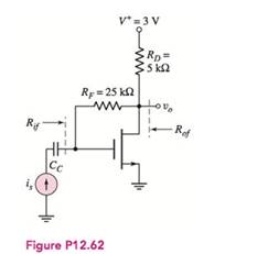
The transistor parameters for the circuit shown in Figure
Want to see the full answer?
Check out a sample textbook solution
Chapter 12 Solutions
Microelectronics: Circuit Analysis and Design


- The transistor parameters for the circuit in Figure are B, =B2 = 100, VBE1on) = VBE2ton) = 0.7 V, and %3D VA1 =VA2 =0.Find the small signal voltage gain Av = vo/vs. (Note that V-=0.026 V) Vcc=9 V Rib Q1 Vs 1 ko -Ro 20 V 100 Q -wwarrow_forwardQ2) Design a voltage-feedback bias circuit using a VCC supply of +10 V, and an npn silicon transistor with B of 100. Choose RC = 6RE=2RB and set IC at 2 mA and the stability factor S(ICO) at 3.arrow_forward6. This problem involves designing a differential amplifier of the following figure. You may assume that the body and source terminal is shorted and you can neglect channel length modulation. Use the following MOSFET parameters: Parameter N-channel P-channel Units +1.10 -1.20 V 5. 2E-5 A/v 1.5E-5 a) Choose IBIAS for an output DC bias level Vo1(Dc) = Voz(DC)=3.00 V. b) Determine the voltage gain of the differential amplifier. c) Determine the magnitude of the small signal common mode gain. VDD = +5V RD1 5kQ RD2 5kO Voi0 o Vo2 M1 M2 W/L=80/2 w/L=80/2 ) IBIAS Vss = -5Varrow_forward
- Consider the circuit of Figure 12.7 on page 605. Assume that VCC=20 V, VBB=0.3 V, RB=40 kΩ, and RC=2 kΩ. The input signal is a 0.2-V-peak 1-kHz sinusoid given by vin(t)=0.2 sin(2000πt). The common-emitter characteristics for the transistor are shown in Figure P12.18. Determine the maximum, minimum, and Q-point values for vCE. What is the approximate voltage gain for this circuit? Why is the gain so small in magnitude?arrow_forwardThe term duty cycle refers to the amount of time a signal is complete cycle. A. off compared to the period of one B. on The output voltage of op-amp is positive saturation, when the voltage applied to the input is greater than the input. A. inverting B. noninverting A square wave that is 20V at its high state and OV when it is off will produce an average DC when its duty cycle is 75%. Formula: VOUT = Duty Cycle * Peak voltage voltage of A. 7.5V B. 10V C. 15Varrow_forwardDraw a n-p-n transistor connected in circuit common base (CB).Draw the input current-voltage characteristic, the output current-voltage characteristicsand the graph giving dependence of the output current as function of the input current.Define the amplification gain of this circuit.arrow_forward
- A) Design with drawing an Op-Amp series voltage regulator to give a regulated O/P voltage of 12V for an I/P of 15V B) Calculate the line regulation if the I/p increases to 4V leads to increase the O/P voltage to 0.02V.arrow_forwardAdiff-amp is biased with a constant-current source lo- 0.25mA that has an output resistance of R. - 8MO. The bipolar transistor parameters are B=100, VT = 0.025 V and VA -. Determine the common-mode input resistance. O a. Ricm = 538 MA O b.Ricm- 308 MO OC Ricm = 808 MO Od Ricm = 704 MQarrow_forwardQ2// Answer the following questions about voltage-feedback bias circuit for the figure below. 1-Determine Ver and VCB. 2- What happens to the voltage Ve if the resistor Rp is open? 22 K 3- What might cause VCE to become nearly 9 V? 4- Determine the change in Ie from 25° to 75° C, if Ico 0.2 HA, and VBE = 0.7V. 10 ul B-80arrow_forward
- Answer the following with illustration and solutions. 2.) If C1 = C2 = 100pF, determine the output frequencies produced by this arrangement:a. (a) when R1 = R2 = 12kilo-ohms andb. (b) when R1 = R2 = 8kilo-ohms See the example below..arrow_forwardDesign an Inverting Summing amplifier to add 0.1 Volt, 0.2 Volt and 0.3 Volt. Vo should be obtained as 6 V. Draw the circuit diagram and derive the expression as wellIarrow_forwardVR2 (t) voltage will be calculated by analyzing the circuit in Figure 2 with a non-linear element using the Small Signal Analysis method. For this purposea) Find the operating point VkQ, IkQ voltage and current values of the nonlinear element.b) Linearize the non-linear element at the operating point.c) Find the voltage VR2 (t) by calculating the effect of the variable source using the linear model.arrow_forward
 Introductory Circuit Analysis (13th Edition)Electrical EngineeringISBN:9780133923605Author:Robert L. BoylestadPublisher:PEARSON
 Delmar's Standard Textbook Of ElectricityElectrical EngineeringISBN:9781337900348Author:Stephen L. HermanPublisher:Cengage Learning
 Programmable Logic ControllersElectrical EngineeringISBN:9780073373843Author:Frank D. PetruzellaPublisher:McGraw-Hill Education
 Fundamentals of Electric CircuitsElectrical EngineeringISBN:9780078028229Author:Charles K Alexander, Matthew SadikuPublisher:McGraw-Hill Education
 Electric Circuits. (11th Edition)Electrical EngineeringISBN:9780134746968Author:James W. Nilsson, Susan RiedelPublisher:PEARSON
 Engineering ElectromagneticsElectrical EngineeringISBN:9780078028151Author:Hayt, William H. (william Hart), Jr, BUCK, John A.Publisher:Mcgraw-hill Education,