
Videos
For the noninverting op-amp circuit in Figure
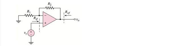
Figure 12.18
Want to see the full answer?
Check out a sample textbook solution
Chapter 12 Solutions
Microelectronics: Circuit Analysis and Design


- +Vcc Vin VI Vo Vref VN -Vcc Ry RxL Figure Q.A2(e). Inverting Schmitt-trigger circuit. (ii) The operational-amplifier (op-amp) of the inverting Schmitt-trigger in Figure Q.A2(e) has saturation voltages of +Vsat = +11 V and -Vsat = -11 V. The voltage divider circuit has the relationship of Rx = 2RY with the value of RY being 100 kn. Using the relationships derived above: (a) Calculate the values of the upper threshold point (UTP or Vi*), lower threshold point (LTP or Vr). (b) Now, sketch the input-output characteristic of the inverting Schmitt- trigger. Clearly label axes, the threshold voltages and the saturation voltages in your sketch.arrow_forwardB- Design a floating current-to-voltage converter that will convert a 4-to20 mA current signal into 0-to 10 V ground-referenced voltage signal. Let the Gain is 5 and feedback resistor (R) is 20 KN.arrow_forwarda) An operational amplifier with non-inverting voltage feedback is given in Figure Q4.a. It has the following properties: Vin + 1 kQ Figure Q4.a Open loop gain: 100,000 Open loop output impedance: 400 Open loop bandwidth: 10 Hz Calculate: 1) The closed-loop voltage gain 2) The closed-loop output impedance 3) The closed-loop bandwidth Vout 99 ΚΩ R₁arrow_forward
- 1- Mention any two non linear applications of op- amp. 2- For the circuit given below : Vin is a sine wave Vinpp=9 V and Vref=2.4 V , Assume Vsat=±12V Name the circuit and draw the input and output waveforms . Vo Vin Vref 3- Explain why open-loop op-amp configurations are not used in linear applications? Draw the block diagram of opamp and define the function of each blockarrow_forward1) Op-amp limiting factors - Current Saturation U2 Vin R1 OUT OPAMP R2 RLoad The saturation output current for the above op-amp is +/- 15mA. For the following input signals, determine if the output appears as would be expected in an ideal circuit. Include sketches of the output voltage. a) R1 = 100, R2 = 900, an open circuit load, and Vin is 2Vpp triangle wave with zero offset voltage (Vmax 1V, Vmin = -1V) and a period of 2ms. b) R1 = 100, R2 = 900, a 1k load, and Vin is 2Vpp triangle wave with a 1V offset voltage (Vmax=2V, Vmin = 0V) and a period of 2ms. c) R1 = 100, R2 = 900, an open circuit load, and Vin is 4Vpp triangle wave with zero offset voltage (Vmax=2V, Vmin = -2V) and a period of 2ms.arrow_forwarda- Zero. b- Slightly different from zero. O Maximum positive or negative. d- An amplified sin wave. 9-Negative feedback reduces @ The feedback fraction. b- Distortion. c- The input offset voltage. d- The open-loop gain. 10-The input impedance of a current-voltage converter is Small. b- Large. c- Ideally zero. d- Ideally infinite. a- 11-In a linear op-amp circuit, the @ Signal are always sin wave. b- Op-amp does not go into saturation. c- Input impedance is ideally infinite. d- Gain-bandwidth product is constant.arrow_forward
- 12.11 Identify each of the op-amp configurations below: Ry Vin W out Va o Ry CourseSmart (a) (b) (c)arrow_forward1- Mention any two advantages of Integrated Circuit . 2- For the circuit given below : Vin is a sine wave Vinpp=6 V and Vref=-2.4 V , Assume Vsat=±12V Name the circuit and draw the input and output waveforms . Vin Vref 3- Explain why open-loop op-amp configurations are not used in linear applications? Draw the block diagram of opamp and define the function of each blockarrow_forwardActivity 2:You are asked to examine the performance of three op-amp circuits. 2-A) Categorize the circuits in terms of using a feedback or not, and the specific type of thefeedback connection (positive or negative, shunt or series, voltage or current).2-B) Explain the principle of operation of Circuit A. Explain limitations of this circuit in termsof practical applications. What is the technical name describing this circuit?2-C) Explain the principle of operation of Circuit B. What is the advantage of this circuitcompared to Circuit A? What is the technical name describing this circuit?2-D) Explain the principle of operation of Circuit C. What is the advantage of this circuitcompared to Circuits A and B? What is the technical name describing this circuit?2-E) Draw the block diagram of Circuit C and define the forward path gain A and feedbackpath gain β. Derive the overall circuit gain relating input to output.2-F) Build all circuits in MultisimTM using one ‘uA741CP‘op-amp IC fed by…arrow_forward
- For the following op-amp circuit (i) (ii) (iii) (iv) R₁ R₂ What is the function of the circuit? Derive the mathematical expression for the closed loop voltage gain What is the high frequency closed loop gain if R₂ = 2.5 k2, R₂ = 50 kN and C = 20 nF? Calculate the cutoff frequencyarrow_forwardAn inverting op-amp circuit has a voltage gain of 10 and a source resistance of 5k. What is the value of the feedback resistors? Note: Enter numeric answer only ohmsarrow_forwardThe open loop gain of an op-amp is 92 dB. Given that the open loop corner frequency is 100 Hz, what is the unity gain bandwidth of the op-amp?arrow_forward
 Introductory Circuit Analysis (13th Edition)Electrical EngineeringISBN:9780133923605Author:Robert L. BoylestadPublisher:PEARSON
 Delmar's Standard Textbook Of ElectricityElectrical EngineeringISBN:9781337900348Author:Stephen L. HermanPublisher:Cengage Learning
 Programmable Logic ControllersElectrical EngineeringISBN:9780073373843Author:Frank D. PetruzellaPublisher:McGraw-Hill Education
 Fundamentals of Electric CircuitsElectrical EngineeringISBN:9780078028229Author:Charles K Alexander, Matthew SadikuPublisher:McGraw-Hill Education
 Electric Circuits. (11th Edition)Electrical EngineeringISBN:9780134746968Author:James W. Nilsson, Susan RiedelPublisher:PEARSON
 Engineering ElectromagneticsElectrical EngineeringISBN:9780078028151Author:Hayt, William H. (william Hart), Jr, BUCK, John A.Publisher:Mcgraw-hill Education,