
Mechanics of Materials, 7th Edition
7th Edition
ISBN: 9780073398235
Author: Ferdinand P. Beer, E. Russell Johnston Jr., John T. DeWolf, David F. Mazurek
Publisher: McGraw-Hill Education
expand_more
expand_more
format_list_bulleted
Concept explainers
Videos
Textbook Question
Chapter 10.1, Problem 22P
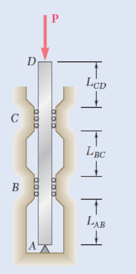
A 1-in.-square aluminum strut is maintained in the position shown by a pin support at A and by sets of rollers at B and C that prevent rotation of the strut in the plane of the figure. Knowing that LAB = 3 ft , determine (a) the largest values of LBC and LCD that can be used if the allowable load P is to be as large as possible, (b) the magnitude of the corresponding allowable load. Consider only buckling in the plane of the figure and use E = 10.4 × 10⁶ psi.
Fig. P10.22 and P10.23
Expert Solution & Answer
Want to see the full answer?
Check out a sample textbook solution
Students have asked these similar questions
Axial loads are applied with rigid bearing plates to the solid cylindrical rods shown. If F₁ = 31 kips, F₂ = 11 kips, F3 = 22 kips, and F4 = 36
kips, determine the absolute value of the axial load in rod (2).
F
A
F₂ (1) F₂
B
F3
C
(3)
D
O 16 kips
O 12 kips
O 7 kips
O 9 kips
O 22 kips
The rigid bars AB and CD shown in Fig. are supported by pins at A
and C and the two rods. Determine the maximum force P that can
be applied if the movement of (P) is limited to 10 mm. Neglect the
wieghts of all members.
Aluminum
L = 2 m
A = 500 mm²
E = 70 GPa
A
3 m
3 m
3 m
0
P
3m
B
Steel
L= 2 m
A = 300 mm²
E = 200 GPa
D
P = 153 KN
P = 133 KN
P = 113 KN
P = 103 kN O
Determine the maximum safe vertical load W that can be supported by the tripod shown in the figure without exceeding a compressive load of 2400 lb in any member.
Answer: W = 5200 lb
Chapter 10 Solutions
Mechanics of Materials, 7th Edition
Ch. 10.1 - Knowing that the spring at A is of constant k and...Ch. 10.1 - Two rigid bars AC and BC are connected by a pin at...Ch. 10.1 - 10.3 and 10.4 Two rigid bars AC and BC are...Ch. 10.1 - 10.3 and 10.4 Two rigid bars AC and BC are...Ch. 10.1 - The steel rod BC is attached to the rigid bar AB...Ch. 10.1 - The rigid rod AB is attached to a hinge at A and...Ch. 10.1 - The rigid bar AD is attached to two springs of...Ch. 10.1 - A frame consists of four L-shaped members...Ch. 10.1 - Determine the critical load of a pin-ended steel...Ch. 10.1 - Determine the critical load of a pin-ended wooden...
Ch. 10.1 - A column of effective length L can be made by...Ch. 10.1 - A compression member of 1.5-m effective length...Ch. 10.1 - Determine the radius of the round strut so that...Ch. 10.1 - Determine (a) the critical load for the square...Ch. 10.1 - A column with the cross section shown has a...Ch. 10.1 - A column is made from half of a W360 216...Ch. 10.1 - A column of 22-ft effective length is made by...Ch. 10.1 - A single compression member of 8.2-m effective...Ch. 10.1 - Knowing that P = 5.2 kN, determine the factor of...Ch. 10.1 - Members AB and CD are 30-mm-diameter steel rods,...Ch. 10.1 - The uniform brass bar AB has a rectangular cross...Ch. 10.1 - A 1-in.-square aluminum strut is maintained in the...Ch. 10.1 - A 1-in.-square aluminum strut is maintained in the...Ch. 10.1 - Column ABC has a uniform rectangular cross section...Ch. 10.1 - Column ABC has a uniform rectangular cross section...Ch. 10.1 - Column AB carries a centric load P of magnitude 15...Ch. 10.1 - Each of the five struts shown consists of a solid...Ch. 10.1 - A rigid block of mass m can be supported in each...Ch. 10.2 - An axial load P = 15 kN is applied at point D that...Ch. 10.2 - An axial load P is applied to the 32-mm-diameter...Ch. 10.2 - The line of action of the 310-kN axial load is...Ch. 10.2 - Prob. 32PCh. 10.2 - An axial load P is applied to the 32-mm-square...Ch. 10.2 - Prob. 34PCh. 10.2 - Prob. 35PCh. 10.2 - Prob. 36PCh. 10.2 - Solve Prob. 10.36, assuming that the axial load P...Ch. 10.2 - The line of action of the axial load P is parallel...Ch. 10.2 - Prob. 39PCh. 10.2 - Prob. 40PCh. 10.2 - The steel bar AB has a 3838-in. square cross...Ch. 10.2 - For the bar of Prob. 10.41, determine the required...Ch. 10.2 - A 3.5-m-long steel tube having the cross section...Ch. 10.2 - Prob. 44PCh. 10.2 - An axial load P is applied to the W8 28...Ch. 10.2 - Prob. 46PCh. 10.2 - A 100-kN axial load P is applied to the W150 18...Ch. 10.2 - A 26-kip axial load P is applied to a W6 12...Ch. 10.2 - Prob. 49PCh. 10.2 - Axial loads of magnitude P = 84 kN are applied...Ch. 10.2 - An axial load of magnitude P = 220 kN is applied...Ch. 10.2 - Prob. 52PCh. 10.2 - Prob. 53PCh. 10.2 - Prob. 54PCh. 10.2 - Axial loads of magnitude P = 175 kN are applied...Ch. 10.2 - Prob. 56PCh. 10.3 - Using allowable stress design, determine the...Ch. 10.3 - Prob. 58PCh. 10.3 - Prob. 59PCh. 10.3 - A column having a 3.5-m effective length is made...Ch. 10.3 - Prob. 61PCh. 10.3 - Bar AB is free at its end A and fixed at its base...Ch. 10.3 - Prob. 63PCh. 10.3 - Prob. 64PCh. 10.3 - A compression member of 8.2-ft effective length is...Ch. 10.3 - A compression member of 9-m effective length is...Ch. 10.3 - A column of 6.4-m effective length is obtained by...Ch. 10.3 - A column of 21-ft effective length is obtained by...Ch. 10.3 - Prob. 69PCh. 10.3 - Prob. 70PCh. 10.3 - Prob. 71PCh. 10.3 - Prob. 72PCh. 10.3 - Prob. 73PCh. 10.3 - For a rod made of aluminum alloy 2014-T6, select...Ch. 10.3 - Prob. 75PCh. 10.3 - Prob. 76PCh. 10.3 - A column of 4.6-m effective length must carry a...Ch. 10.3 - A column of 22.5-ft effective length must carry a...Ch. 10.3 - Prob. 79PCh. 10.3 - A centric load P must be supported by the steel...Ch. 10.3 - A square steel tube having the cross section shown...Ch. 10.3 - Prob. 82PCh. 10.3 - Prob. 83PCh. 10.3 - Two 89 64-mm angles are bolted together as shown...Ch. 10.3 - Prob. 85PCh. 10.3 - Prob. 86PCh. 10.3 - Prob. 87PCh. 10.3 - Prob. 88PCh. 10.4 - An eccentric load is applied at a point 22 mm from...Ch. 10.4 - Prob. 90PCh. 10.4 - Prob. 91PCh. 10.4 - Solve Prob. 10.91 using the interaction method and...Ch. 10.4 - A column of 5.5-m effective length is made of the...Ch. 10.4 - Prob. 94PCh. 10.4 - A steel compression member of 9-ft effective...Ch. 10.4 - Prob. 96PCh. 10.4 - Two L4 3 38-in. steel angles are welded together...Ch. 10.4 - Solve Prob. 10.97 using the interaction method...Ch. 10.4 - A rectangular column is made of a grade of sawn...Ch. 10.4 - Prob. 100PCh. 10.4 - Prob. 101PCh. 10.4 - Prob. 102PCh. 10.4 - Prob. 103PCh. 10.4 - Prob. 104PCh. 10.4 - A steel tube of 80-mm outer diameter is to carry a...Ch. 10.4 - Prob. 106PCh. 10.4 - Prob. 107PCh. 10.4 - Prob. 108PCh. 10.4 - Prob. 109PCh. 10.4 - Prob. 110PCh. 10.4 - Prob. 111PCh. 10.4 - Prob. 112PCh. 10.4 - Prob. 113PCh. 10.4 - Prob. 114PCh. 10.4 - Prob. 115PCh. 10.4 - A steel column of 7.2-m effective length is to...Ch. 10 - Determine (a) the critical load for the steel...Ch. 10 - Prob. 118RPCh. 10 - Prob. 119RPCh. 10 - (a) Considering only buckling in the plane of the...Ch. 10 - Member AB consists of a single C130 3 10.4 steel...Ch. 10 - The line of action of the 75-kip axial load is...Ch. 10 - Prob. 123RPCh. 10 - Prob. 124RPCh. 10 - A rectangular column with a 4.4-m effective length...Ch. 10 - Prob. 126RPCh. 10 - Prob. 127RPCh. 10 - Prob. 128RP
Knowledge Booster


Learn more about
Need a deep-dive on the concept behind this application? Look no further. Learn more about this topic, mechanical-engineering and related others by exploring similar questions and additional content below.Similar questions
- PROBLEM: The cable and boom system shown support a load of 555 N. Determine the tensile force Tin the cable and the compressive force Cin the boom. 555 27° 32°arrow_forwardTwo solid cylindrical rods support a load of P = 19 kN as shown. Determine the axial load in rod (1). 3.8 m 4.6 m (1) 5.6 m 3.3 m 18.15 KN 20.03 KN 21.56 kN 15.44 kN 14.52 KN B (2)arrow_forwardTask 2. The non-deformable, homogeneous ABCD board with a weight of G=10 kN is supported by three steel articulated bars BK, CH, DH and loaded with a horizontal force P=20 kN. Determine the value of the diameters of the bars, if the allowable tensile stress kr=10 kN/cm, a=1 m, b = 0.8 m. K H В P a |G A a Darrow_forward
- Axial loads are applied with rigid bearing plates to the solid cylindrical rods shown. If F₁ = 30 kips, F₂ = 14 kips, F3 = 20 kips, and F4 = 39 kips, determine the absolute value of the axial load in rod (2). EVOVE F3 (2) (3) A O 24 kips O 18 kips O 21 kips 28 kips O 17 kips B F3 F4 C Darrow_forwardThe truss below is subject to the loads as shown. All of the members are attached at plates and can be treated as pin connected. The truss is attached to the ground at a pin joint at G and a roller at D. The applied load H is 357 N. The applied load J is 321 N. What is the internal resultant normal force in member AE in N? (tension is positive, compression is negative) E F G A 3 m B Η. 3 m 3 m D 5 marrow_forwardTwo solid cylindrical rods support a load of P = 17 kN as shown. Determine the axial load in rod (1).arrow_forward
- Q2. The pin-connected frame is subjected to the force Fas shown. The dimensions are 4-4.0 ft, - 2.6 ft. and -3.9 ft. Member BC is made of steel (E- 29000 ksi), and has rectangular cross-section, with b- 13 in. and h=4.1 in. The supports at B and Cact as pins for x-x axis buckling and as fixed supports for y yaxis buckling. Determine the greatest load F(in the unit of kip) the beam will support without causing member BC to buckle. Please pay attention: the numbers may change since they are randomized. Your answer must include 2 places after the decimal point. Your Answer:arrow_forwardThe bars AB, AC, and AD are pinned together as shown in the Horizontal movement of the pin at A is prevented by the rigid horizontal strut AE. Calculate the axial force in the strut caused by the 10-kip load. For each steel bar, A = 0.3 in.2 and E = 29 x 106 psi. For the aluminum bar, A = 0.6 in.2 and E = 10 x 106 psi.arrow_forwardAxial loads are applied with rigid bearing plates to the solid cylindrical rods shown. If F₁ = 33 kips, F₂ = 18 kips, F3 = 25 kips, and F4 = 38 kips, determine the absolute value of the axial load in rod (2). F₁ A F₂ (1) F₂ B F3 (3) F3 F₁ с D O 21 kips 16 kips 29 kips 25 kips O 19 kipsarrow_forward
- A uniformly-distributed load w is supported by a structure consisting of rigid bar BDF and three rods. Rods (1) and (2) are 15-mm- diameter stainless steel rods that have an elastic modulus of E= 191 GPa. Rod (3) is a 21-mm-diameter bronze rod that has an elastic modulus of E= 100 GPa. Use a = 1.6 m and L = 3.2 m. For a load magnitude of w= 32 kN/m, calculate (a) the normal stress in each rod. (b) the vertical deflection of the rigid bar at F. (1) B Answers: (a) σ₁ = i (b) VF= i D Save for Later (2) eTextbook and Media 2a W E MPa, σ₂ = i mm MPa, and σ3 = i Attempts: 0 of 5 used MPa Submit Answerarrow_forwardQ1: The rigid bar ABC, attached to two vertical rods as shown in Fig. below, is horizontal before the load P is applied. Determine the vertical movement at point B if P magnitude is 45 kN. Aluminum L= 3 m A = 500 mm? E = 70 GPa Steel L= 4 m A = 300 mm E = 200 GPa B 3.5 m 2.5 marrow_forwardTwo solid cylindrical rods support a load of P = 25 kN as shown. Determine the axial load in rod (1). 3.8 m 4.6 m (1) 5.6 m (2) 3.3 m 28.01 kN 19.30 KN 26.06 kN 16.60 kN O 20.32 kN B Parrow_forward
arrow_back_ios
SEE MORE QUESTIONS
arrow_forward_ios
Recommended textbooks for you
 Elements Of ElectromagneticsMechanical EngineeringISBN:9780190698614Author:Sadiku, Matthew N. O.Publisher:Oxford University Press
 Mechanics of Materials (10th Edition)Mechanical EngineeringISBN:9780134319650Author:Russell C. HibbelerPublisher:PEARSON
 Thermodynamics: An Engineering ApproachMechanical EngineeringISBN:9781259822674Author:Yunus A. Cengel Dr., Michael A. BolesPublisher:McGraw-Hill Education
 Control Systems EngineeringMechanical EngineeringISBN:9781118170519Author:Norman S. NisePublisher:WILEY
 Mechanics of Materials (MindTap Course List)Mechanical EngineeringISBN:9781337093347Author:Barry J. Goodno, James M. GerePublisher:Cengage Learning
 Engineering Mechanics: StaticsMechanical EngineeringISBN:9781118807330Author:James L. Meriam, L. G. Kraige, J. N. BoltonPublisher:WILEY
Elements Of Electromagnetics
Mechanical Engineering
ISBN:9780190698614
Author:Sadiku, Matthew N. O.
Publisher:Oxford University Press
Mechanics of Materials (10th Edition)
Mechanical Engineering
ISBN:9780134319650
Author:Russell C. Hibbeler
Publisher:PEARSON
Thermodynamics: An Engineering Approach
Mechanical Engineering
ISBN:9781259822674
Author:Yunus A. Cengel Dr., Michael A. Boles
Publisher:McGraw-Hill Education
Control Systems Engineering
Mechanical Engineering
ISBN:9781118170519
Author:Norman S. Nise
Publisher:WILEY
Mechanics of Materials (MindTap Course List)
Mechanical Engineering
ISBN:9781337093347
Author:Barry J. Goodno, James M. Gere
Publisher:Cengage Learning
Engineering Mechanics: Statics
Mechanical Engineering
ISBN:9781118807330
Author:James L. Meriam, L. G. Kraige, J. N. Bolton
Publisher:WILEY
Column buckling; Author: Amber Book;https://www.youtube.com/watch?v=AvvaCi_Nn94;License: Standard Youtube License