
Mechanics of Materials, 7th Edition
7th Edition
ISBN: 9780073398235
Author: Ferdinand P. Beer, E. Russell Johnston Jr., John T. DeWolf, David F. Mazurek
Publisher: McGraw-Hill Education
expand_more
expand_more
format_list_bulleted
Concept explainers
Videos
Textbook Question
Chapter 10.2, Problem 43P
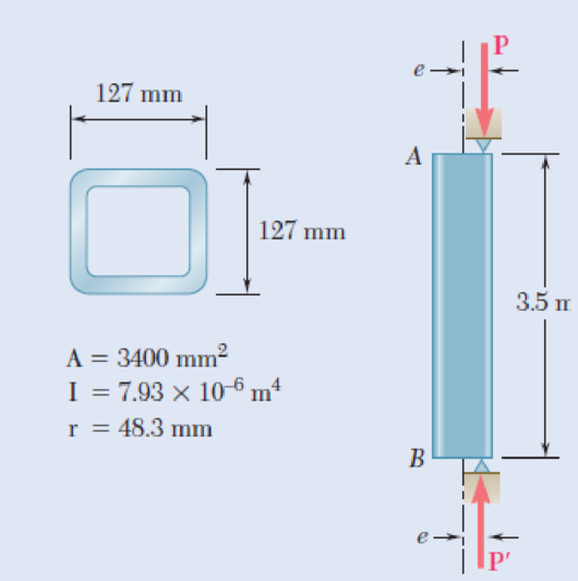
A 3.5-m-long steel tube having the cross section and properties shown is used as a column. For the grade of steel used σY = 250 MPa and E = 200 GPa. Knowing that a factor of safety of 2.6 with respect to permanent deformation is required, determine the allowable load P when the eccentricity e is (a) 15 mm, (b) 7.5 mm. (Hint: Since the factor of safety must be applied to the load P, not to the stress, use Fig. 10.24 to determine PY).
Fig. P10.43
Expert Solution & Answer
Want to see the full answer?
Check out a sample textbook solution
Students have asked these similar questions
Determine the largest axial load P that can be safely supported by a flat steel bar consisting of two portions, both 10 mm thick and, respectively, 40 and 60 mm wide, connected by fillets of radius r=8 mm. Assume an allowable normal stress of 165 MPa.
Two gage marks are placed exactly 10 in. apart on a 1⁄2-in.-diameter aluminum rod with E = 10.1 x 10⁶ psi and an ultimate strength of 16 ksi. Knowing that the distance between the gage marks is 10.009 in. after a load isapplied, determine
(a) the stress in the rod,
(b) the factor of safety,
(c) the corresponding normal stress in thewire.
In the steel structure shown, a 6-mm-diameter pin is used at C and10-mm-diameter pins are used at B and D. The ultimate shearing stress is 150 MPa at all connections, and the ultimate normal stress is 400 MPa in link BD. Knowing that a factor of safety of 3.0 is desired,determine the largest load P that can be applied at A. Note that link BD is not reinforced around the pin holes.
Chapter 10 Solutions
Mechanics of Materials, 7th Edition
Ch. 10.1 - Knowing that the spring at A is of constant k and...Ch. 10.1 - Two rigid bars AC and BC are connected by a pin at...Ch. 10.1 - 10.3 and 10.4 Two rigid bars AC and BC are...Ch. 10.1 - 10.3 and 10.4 Two rigid bars AC and BC are...Ch. 10.1 - The steel rod BC is attached to the rigid bar AB...Ch. 10.1 - The rigid rod AB is attached to a hinge at A and...Ch. 10.1 - The rigid bar AD is attached to two springs of...Ch. 10.1 - A frame consists of four L-shaped members...Ch. 10.1 - Determine the critical load of a pin-ended steel...Ch. 10.1 - Determine the critical load of a pin-ended wooden...
Ch. 10.1 - A column of effective length L can be made by...Ch. 10.1 - A compression member of 1.5-m effective length...Ch. 10.1 - Determine the radius of the round strut so that...Ch. 10.1 - Determine (a) the critical load for the square...Ch. 10.1 - A column with the cross section shown has a...Ch. 10.1 - A column is made from half of a W360 216...Ch. 10.1 - A column of 22-ft effective length is made by...Ch. 10.1 - A single compression member of 8.2-m effective...Ch. 10.1 - Knowing that P = 5.2 kN, determine the factor of...Ch. 10.1 - Members AB and CD are 30-mm-diameter steel rods,...Ch. 10.1 - The uniform brass bar AB has a rectangular cross...Ch. 10.1 - A 1-in.-square aluminum strut is maintained in the...Ch. 10.1 - A 1-in.-square aluminum strut is maintained in the...Ch. 10.1 - Column ABC has a uniform rectangular cross section...Ch. 10.1 - Column ABC has a uniform rectangular cross section...Ch. 10.1 - Column AB carries a centric load P of magnitude 15...Ch. 10.1 - Each of the five struts shown consists of a solid...Ch. 10.1 - A rigid block of mass m can be supported in each...Ch. 10.2 - An axial load P = 15 kN is applied at point D that...Ch. 10.2 - An axial load P is applied to the 32-mm-diameter...Ch. 10.2 - The line of action of the 310-kN axial load is...Ch. 10.2 - Prob. 32PCh. 10.2 - An axial load P is applied to the 32-mm-square...Ch. 10.2 - Prob. 34PCh. 10.2 - Prob. 35PCh. 10.2 - Prob. 36PCh. 10.2 - Solve Prob. 10.36, assuming that the axial load P...Ch. 10.2 - The line of action of the axial load P is parallel...Ch. 10.2 - Prob. 39PCh. 10.2 - Prob. 40PCh. 10.2 - The steel bar AB has a 3838-in. square cross...Ch. 10.2 - For the bar of Prob. 10.41, determine the required...Ch. 10.2 - A 3.5-m-long steel tube having the cross section...Ch. 10.2 - Prob. 44PCh. 10.2 - An axial load P is applied to the W8 28...Ch. 10.2 - Prob. 46PCh. 10.2 - A 100-kN axial load P is applied to the W150 18...Ch. 10.2 - A 26-kip axial load P is applied to a W6 12...Ch. 10.2 - Prob. 49PCh. 10.2 - Axial loads of magnitude P = 84 kN are applied...Ch. 10.2 - An axial load of magnitude P = 220 kN is applied...Ch. 10.2 - Prob. 52PCh. 10.2 - Prob. 53PCh. 10.2 - Prob. 54PCh. 10.2 - Axial loads of magnitude P = 175 kN are applied...Ch. 10.2 - Prob. 56PCh. 10.3 - Using allowable stress design, determine the...Ch. 10.3 - Prob. 58PCh. 10.3 - Prob. 59PCh. 10.3 - A column having a 3.5-m effective length is made...Ch. 10.3 - Prob. 61PCh. 10.3 - Bar AB is free at its end A and fixed at its base...Ch. 10.3 - Prob. 63PCh. 10.3 - Prob. 64PCh. 10.3 - A compression member of 8.2-ft effective length is...Ch. 10.3 - A compression member of 9-m effective length is...Ch. 10.3 - A column of 6.4-m effective length is obtained by...Ch. 10.3 - A column of 21-ft effective length is obtained by...Ch. 10.3 - Prob. 69PCh. 10.3 - Prob. 70PCh. 10.3 - Prob. 71PCh. 10.3 - Prob. 72PCh. 10.3 - Prob. 73PCh. 10.3 - For a rod made of aluminum alloy 2014-T6, select...Ch. 10.3 - Prob. 75PCh. 10.3 - Prob. 76PCh. 10.3 - A column of 4.6-m effective length must carry a...Ch. 10.3 - A column of 22.5-ft effective length must carry a...Ch. 10.3 - Prob. 79PCh. 10.3 - A centric load P must be supported by the steel...Ch. 10.3 - A square steel tube having the cross section shown...Ch. 10.3 - Prob. 82PCh. 10.3 - Prob. 83PCh. 10.3 - Two 89 64-mm angles are bolted together as shown...Ch. 10.3 - Prob. 85PCh. 10.3 - Prob. 86PCh. 10.3 - Prob. 87PCh. 10.3 - Prob. 88PCh. 10.4 - An eccentric load is applied at a point 22 mm from...Ch. 10.4 - Prob. 90PCh. 10.4 - Prob. 91PCh. 10.4 - Solve Prob. 10.91 using the interaction method and...Ch. 10.4 - A column of 5.5-m effective length is made of the...Ch. 10.4 - Prob. 94PCh. 10.4 - A steel compression member of 9-ft effective...Ch. 10.4 - Prob. 96PCh. 10.4 - Two L4 3 38-in. steel angles are welded together...Ch. 10.4 - Solve Prob. 10.97 using the interaction method...Ch. 10.4 - A rectangular column is made of a grade of sawn...Ch. 10.4 - Prob. 100PCh. 10.4 - Prob. 101PCh. 10.4 - Prob. 102PCh. 10.4 - Prob. 103PCh. 10.4 - Prob. 104PCh. 10.4 - A steel tube of 80-mm outer diameter is to carry a...Ch. 10.4 - Prob. 106PCh. 10.4 - Prob. 107PCh. 10.4 - Prob. 108PCh. 10.4 - Prob. 109PCh. 10.4 - Prob. 110PCh. 10.4 - Prob. 111PCh. 10.4 - Prob. 112PCh. 10.4 - Prob. 113PCh. 10.4 - Prob. 114PCh. 10.4 - Prob. 115PCh. 10.4 - A steel column of 7.2-m effective length is to...Ch. 10 - Determine (a) the critical load for the steel...Ch. 10 - Prob. 118RPCh. 10 - Prob. 119RPCh. 10 - (a) Considering only buckling in the plane of the...Ch. 10 - Member AB consists of a single C130 3 10.4 steel...Ch. 10 - The line of action of the 75-kip axial load is...Ch. 10 - Prob. 123RPCh. 10 - Prob. 124RPCh. 10 - A rectangular column with a 4.4-m effective length...Ch. 10 - Prob. 126RPCh. 10 - Prob. 127RPCh. 10 - Prob. 128RP
Knowledge Booster


Learn more about
Need a deep-dive on the concept behind this application? Look no further. Learn more about this topic, mechanical-engineering and related others by exploring similar questions and additional content below.Similar questions
- A square aluminum bar should not stretch more than 1.4 mm when it is subjected to a tensile load.Knowing that E = 70 GPa and that the allowable tensile strength is 120 MPa, determine the maximumallowable length.arrow_forwardA 9 kN tensile load will be applied to a 50 m length of steel wire with E=200 GPa. Knowing that the normal stress must not exceed 150 MPa and that the increase in the length of the wire should be at most 25 mm, determine the smallest diameter wire which can be used.arrow_forwardA pin-connected structure is supported and loaded as shown. Member ABCD is rigid and is horizontal before the load P is applied. Bars (1) and (2) are both made from steel [E = 30,000 ksi] and both have a cross-sectional area of 1.25 in.?. If the normal stress in bar (1) must be limited to 31 ksi, determine the maximum load P that may be applied to the rigid bar. 120 in. 80 in. (2) (1) B D 54 in. 54 in. 24 in. Parrow_forward
- ! Required information Each of the five struts shown consists of a solid steel rod with E= 200 GPa. Given: Po = 7.2 kN 900 mm Po (1) Po (2) Po (3) (5) Knowing that the strut of Fig. (1) is of a 20-mm diameter, determine the factor of safety with respect to buckling for the loading shown. (Round the final answer to two decimal places. You must provide an answer before moving the the next part.) The factor of safety isarrow_forwardA timber column, 8 in. by 8 in. in cross section, is reinforced on all four sides by steel plates, each plate being 8 in. wide and t in. thick. Determine the smallest value of tfor which the column can support an axial load of 300 kips if the working stresses are 1200 psi for timber and 20 ksi for steel. The moduli of elasticity are 1.5 x10⁶psi for timber and 29 x 106psi for steel.arrow_forwardThe ABC element is supported by a pin at C and a BD cable. Knowing that the limit load for the BD cable is 150 kN, and the coefficient Safety with respect to cable failure for BD of 3.5 determine the maximum value of the load P that can be supported. Determine the diameter of pin C, knowing that it is made of steel with an admissible stress of σadm = 270 Mpa, and that it is subjected to shear double.arrow_forward
- (4) The shown cast-iron bracket has an ultimate compressive strength of 504 MPa and an ultimate tensile strength of 225 MPa. Given that the minimum material factor of safety needed is 1.5, it is required to: (a) Determine the maximum force P that can be supported by the bracket. (b) Draw the normal stress distribution at section ABD at this load value. 22 mm 50 mm D 15 mm 15 mmarrow_forwardThe aluminum rod ABC (E = 10.1 × 10⁶ psi), which consists of two cylindrical portions AB and BC, is to be replaced with a cylindrical steel rod DE (E = 29 × 106 psi) of the same overall length. Determine the minimum required diameter d of the steel rod if its vertical deformation is not to exceed the deformation of the aluminum rod under the same load and if the allowable stress in the steel rod is not to exceed 27 ksi. The minimum required diameter of the steel rod is in.arrow_forwardA 12-kN tensile load will be applied to a 50-m length of steel wire with E= 200 GPa. Determine the smallest diameter wire that can be used, knowing that the normal stress must not exceed 150 MPa and that the increase in length of the wire must not exceed 25 mm. The smallest diameter that can be used is mm.arrow_forward
- In the structure shown, an 8-mm diameter pin is used at A, and 12- mm diameter pins are used at B and D. Knowing that the ultimate shearing stresses is 100 MPa at all connections and that the ultimate normal stress is 250 MPa in each of the two links joining B and D, determine the allowable load P if an overall factor of safety of 3.0 is desired.arrow_forward2. The assembly shown below is subjected to the load P applied at 30°. The cylindrical pins at A, B, C, D, and E are identical and made of the same material whose allowable shear stress Tallow = 40.0 MPa and has a diameter of d = 3.0 mm. Determine the maximum load P that can be applied. 1 m 1 m P C 30 B. 45° 3 marrow_forwardA timber block 250 mm square is reinforced on each side by a steel plate 250 mm wide and t mm thick. Determine the thickness t so that the assembly will support an axial load of 1200 kN without exceeding a maximum timber stress of 8 Mpa or a maximum steel stress of 140 Mpa. For timber, E = 10 x 103 Mpa; for steel, E = 200 x 103 Mpa.arrow_forward
arrow_back_ios
SEE MORE QUESTIONS
arrow_forward_ios
Recommended textbooks for you
 Elements Of ElectromagneticsMechanical EngineeringISBN:9780190698614Author:Sadiku, Matthew N. O.Publisher:Oxford University Press
 Mechanics of Materials (10th Edition)Mechanical EngineeringISBN:9780134319650Author:Russell C. HibbelerPublisher:PEARSON
 Thermodynamics: An Engineering ApproachMechanical EngineeringISBN:9781259822674Author:Yunus A. Cengel Dr., Michael A. BolesPublisher:McGraw-Hill Education
 Control Systems EngineeringMechanical EngineeringISBN:9781118170519Author:Norman S. NisePublisher:WILEY
 Mechanics of Materials (MindTap Course List)Mechanical EngineeringISBN:9781337093347Author:Barry J. Goodno, James M. GerePublisher:Cengage Learning
 Engineering Mechanics: StaticsMechanical EngineeringISBN:9781118807330Author:James L. Meriam, L. G. Kraige, J. N. BoltonPublisher:WILEY
Elements Of Electromagnetics
Mechanical Engineering
ISBN:9780190698614
Author:Sadiku, Matthew N. O.
Publisher:Oxford University Press
Mechanics of Materials (10th Edition)
Mechanical Engineering
ISBN:9780134319650
Author:Russell C. Hibbeler
Publisher:PEARSON
Thermodynamics: An Engineering Approach
Mechanical Engineering
ISBN:9781259822674
Author:Yunus A. Cengel Dr., Michael A. Boles
Publisher:McGraw-Hill Education
Control Systems Engineering
Mechanical Engineering
ISBN:9781118170519
Author:Norman S. Nise
Publisher:WILEY
Mechanics of Materials (MindTap Course List)
Mechanical Engineering
ISBN:9781337093347
Author:Barry J. Goodno, James M. Gere
Publisher:Cengage Learning
Engineering Mechanics: Statics
Mechanical Engineering
ISBN:9781118807330
Author:James L. Meriam, L. G. Kraige, J. N. Bolton
Publisher:WILEY
Column buckling; Author: Amber Book;https://www.youtube.com/watch?v=AvvaCi_Nn94;License: Standard Youtube License