
Mechanics of Materials, 7th Edition
7th Edition
ISBN: 9780073398235
Author: Ferdinand P. Beer, E. Russell Johnston Jr., John T. DeWolf, David F. Mazurek
Publisher: McGraw-Hill Education
expand_more
expand_more
format_list_bulleted
Concept explainers
Videos
Textbook Question
Chapter 10.1, Problem 16P
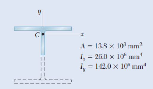
A column is made from half of a W360 × 216 rolled-steel shape, with the geometric properties as shown. Using a factor of safety equal to 2.6, determine the allowable centric load if the effective length of the column is 6.5 m. Use E = 200 GPa.
Fig. P10.16
Expert Solution & Answer
Want to see the full answer?
Check out a sample textbook solution
Students have asked these similar questions
7. Select the lightest W shape that will act as a column 8 m long with hinged
ends and support an axial load of 270 kN with a factor of safety of 2.5.
Assume that the proportional limit is 200 MPa and E = 200 GPa.
Ans L = 13.98 m, F = 1476 kN
Show all work and units
An aluminum strut 2.50m long has a rectangular section 60mm by 30mm. A bolt through each end secures the strut so that it acts as a hinged column about an axis perpendicular to the 60 mm dimension and as a fixed ended column about an axis perpendicular to the 30mm dimension. Determine the safe central load using a factor of safety of 2.5 and E = 70 Gpa.
Chapter 10 Solutions
Mechanics of Materials, 7th Edition
Ch. 10.1 - Knowing that the spring at A is of constant k and...Ch. 10.1 - Two rigid bars AC and BC are connected by a pin at...Ch. 10.1 - 10.3 and 10.4 Two rigid bars AC and BC are...Ch. 10.1 - 10.3 and 10.4 Two rigid bars AC and BC are...Ch. 10.1 - The steel rod BC is attached to the rigid bar AB...Ch. 10.1 - The rigid rod AB is attached to a hinge at A and...Ch. 10.1 - The rigid bar AD is attached to two springs of...Ch. 10.1 - A frame consists of four L-shaped members...Ch. 10.1 - Determine the critical load of a pin-ended steel...Ch. 10.1 - Determine the critical load of a pin-ended wooden...
Ch. 10.1 - A column of effective length L can be made by...Ch. 10.1 - A compression member of 1.5-m effective length...Ch. 10.1 - Determine the radius of the round strut so that...Ch. 10.1 - Determine (a) the critical load for the square...Ch. 10.1 - A column with the cross section shown has a...Ch. 10.1 - A column is made from half of a W360 216...Ch. 10.1 - A column of 22-ft effective length is made by...Ch. 10.1 - A single compression member of 8.2-m effective...Ch. 10.1 - Knowing that P = 5.2 kN, determine the factor of...Ch. 10.1 - Members AB and CD are 30-mm-diameter steel rods,...Ch. 10.1 - The uniform brass bar AB has a rectangular cross...Ch. 10.1 - A 1-in.-square aluminum strut is maintained in the...Ch. 10.1 - A 1-in.-square aluminum strut is maintained in the...Ch. 10.1 - Column ABC has a uniform rectangular cross section...Ch. 10.1 - Column ABC has a uniform rectangular cross section...Ch. 10.1 - Column AB carries a centric load P of magnitude 15...Ch. 10.1 - Each of the five struts shown consists of a solid...Ch. 10.1 - A rigid block of mass m can be supported in each...Ch. 10.2 - An axial load P = 15 kN is applied at point D that...Ch. 10.2 - An axial load P is applied to the 32-mm-diameter...Ch. 10.2 - The line of action of the 310-kN axial load is...Ch. 10.2 - Prob. 32PCh. 10.2 - An axial load P is applied to the 32-mm-square...Ch. 10.2 - Prob. 34PCh. 10.2 - Prob. 35PCh. 10.2 - Prob. 36PCh. 10.2 - Solve Prob. 10.36, assuming that the axial load P...Ch. 10.2 - The line of action of the axial load P is parallel...Ch. 10.2 - Prob. 39PCh. 10.2 - Prob. 40PCh. 10.2 - The steel bar AB has a 3838-in. square cross...Ch. 10.2 - For the bar of Prob. 10.41, determine the required...Ch. 10.2 - A 3.5-m-long steel tube having the cross section...Ch. 10.2 - Prob. 44PCh. 10.2 - An axial load P is applied to the W8 28...Ch. 10.2 - Prob. 46PCh. 10.2 - A 100-kN axial load P is applied to the W150 18...Ch. 10.2 - A 26-kip axial load P is applied to a W6 12...Ch. 10.2 - Prob. 49PCh. 10.2 - Axial loads of magnitude P = 84 kN are applied...Ch. 10.2 - An axial load of magnitude P = 220 kN is applied...Ch. 10.2 - Prob. 52PCh. 10.2 - Prob. 53PCh. 10.2 - Prob. 54PCh. 10.2 - Axial loads of magnitude P = 175 kN are applied...Ch. 10.2 - Prob. 56PCh. 10.3 - Using allowable stress design, determine the...Ch. 10.3 - Prob. 58PCh. 10.3 - Prob. 59PCh. 10.3 - A column having a 3.5-m effective length is made...Ch. 10.3 - Prob. 61PCh. 10.3 - Bar AB is free at its end A and fixed at its base...Ch. 10.3 - Prob. 63PCh. 10.3 - Prob. 64PCh. 10.3 - A compression member of 8.2-ft effective length is...Ch. 10.3 - A compression member of 9-m effective length is...Ch. 10.3 - A column of 6.4-m effective length is obtained by...Ch. 10.3 - A column of 21-ft effective length is obtained by...Ch. 10.3 - Prob. 69PCh. 10.3 - Prob. 70PCh. 10.3 - Prob. 71PCh. 10.3 - Prob. 72PCh. 10.3 - Prob. 73PCh. 10.3 - For a rod made of aluminum alloy 2014-T6, select...Ch. 10.3 - Prob. 75PCh. 10.3 - Prob. 76PCh. 10.3 - A column of 4.6-m effective length must carry a...Ch. 10.3 - A column of 22.5-ft effective length must carry a...Ch. 10.3 - Prob. 79PCh. 10.3 - A centric load P must be supported by the steel...Ch. 10.3 - A square steel tube having the cross section shown...Ch. 10.3 - Prob. 82PCh. 10.3 - Prob. 83PCh. 10.3 - Two 89 64-mm angles are bolted together as shown...Ch. 10.3 - Prob. 85PCh. 10.3 - Prob. 86PCh. 10.3 - Prob. 87PCh. 10.3 - Prob. 88PCh. 10.4 - An eccentric load is applied at a point 22 mm from...Ch. 10.4 - Prob. 90PCh. 10.4 - Prob. 91PCh. 10.4 - Solve Prob. 10.91 using the interaction method and...Ch. 10.4 - A column of 5.5-m effective length is made of the...Ch. 10.4 - Prob. 94PCh. 10.4 - A steel compression member of 9-ft effective...Ch. 10.4 - Prob. 96PCh. 10.4 - Two L4 3 38-in. steel angles are welded together...Ch. 10.4 - Solve Prob. 10.97 using the interaction method...Ch. 10.4 - A rectangular column is made of a grade of sawn...Ch. 10.4 - Prob. 100PCh. 10.4 - Prob. 101PCh. 10.4 - Prob. 102PCh. 10.4 - Prob. 103PCh. 10.4 - Prob. 104PCh. 10.4 - A steel tube of 80-mm outer diameter is to carry a...Ch. 10.4 - Prob. 106PCh. 10.4 - Prob. 107PCh. 10.4 - Prob. 108PCh. 10.4 - Prob. 109PCh. 10.4 - Prob. 110PCh. 10.4 - Prob. 111PCh. 10.4 - Prob. 112PCh. 10.4 - Prob. 113PCh. 10.4 - Prob. 114PCh. 10.4 - Prob. 115PCh. 10.4 - A steel column of 7.2-m effective length is to...Ch. 10 - Determine (a) the critical load for the steel...Ch. 10 - Prob. 118RPCh. 10 - Prob. 119RPCh. 10 - (a) Considering only buckling in the plane of the...Ch. 10 - Member AB consists of a single C130 3 10.4 steel...Ch. 10 - The line of action of the 75-kip axial load is...Ch. 10 - Prob. 123RPCh. 10 - Prob. 124RPCh. 10 - A rectangular column with a 4.4-m effective length...Ch. 10 - Prob. 126RPCh. 10 - Prob. 127RPCh. 10 - Prob. 128RP
Knowledge Booster


Learn more about
Need a deep-dive on the concept behind this application? Look no further. Learn more about this topic, mechanical-engineering and related others by exploring similar questions and additional content below.Similar questions
- A column with the cross section shown has a 13.5-ft effective length. Using a factor of safety equal to 2.8, determine the allowable centric load that can be applied to the column. Use E= 29 x106 psi.arrow_forwardWITH DESCRIPTION AND STEPS APPLIED, TO HELP ME UNDERSTAND APPROPRIATELYarrow_forwardShow all work and unitsarrow_forward
- Question 3 A column of 7 m effective length is to be made by welding two 228 x 12 mm plates to a W200 x 52 as shown. Determine the allowable centric load if a factor of safety of 2.3 is required. Use E = 200 GPa. For an W200 x 52 section, IÂ =(52.7×10°)mmª, I„ = (17.8×10°)mmª . 114 mm 114 mm Ⓒ xarrow_forwardA compression member of 1.5-m effective length consists of a solid 30-mm-diameter brass rod. In order to reduce the weight of the member by 25%, the solid rod is replaced by a hollow rod of the cross section shown. 15 mm Determine (a) the percent reduction in the critical load, (b) the value of the critical load for the hollow rod. Use E = 200 GPa. 30 mm 30 mmarrow_forwardA column with the cross section shown has a 13.5-ft effective length. Using a factor of safety equal to 3, determine the allowable centric load that can be applied to the column. Use E= 29 × 106 psi. (Round the final answer to one decimal place.) in.- 6 in. 10 in. in. in. The allowable centric load that can be applied to the column is kips.arrow_forward
- A uniformly-distributed load w is supported by a structure consisting of rigid bar BDF and three rods. Rods (1) and (2) are 15-mm- diameter stainless steel rods that have an elastic modulus of E= 191 GPa. Rod (3) is a 21-mm-diameter bronze rod that has an elastic modulus of E= 100 GPa. Use a = 1.6 m and L = 3.2 m. For a load magnitude of w= 32 kN/m, calculate (a) the normal stress in each rod. (b) the vertical deflection of the rigid bar at F. (1) B Answers: (a) σ₁ = i (b) VF= i D Save for Later (2) eTextbook and Media 2a W E MPa, σ₂ = i mm MPa, and σ3 = i Attempts: 0 of 5 used MPa Submit Answerarrow_forwardTwo brass rods used as compression members, each of 3-m effective length, have the cross sections shown. (a) Determine the wall thick-ness of the hollow square rod for which the rods have the same cross-sectional area. (b) Using E= 105 GPa, determine the critical load of each rod.arrow_forwardDetermine (a) the critical load for the brass stut, (b) the dimension d for which the aluminum strut will have the same critical load, (c) the weight of the aluminum strut as a percent of the weight of the brass strut.arrow_forward
- Determine the critical load of a pin-ended wooden stick that is 3 ft long and has a 3/16 × 1 1/4-in. rectangular cross section. Use E = 1.6 × 10⁶ psi. (Round the final answer to two decimal places.)arrow_forwardA 16-ft-long column that is effectively pin-supported at both ends can be made by gluing together three identical 1.5" x 4.5" planks in either of the two configurations shown. Determine the Euler critical load for each configuration. The planks are 4.5 in. Douglas fir (E = 1900 ksi). - - 1.5 in. (a) (b)arrow_forwardA column of 22.5-ft effective length must carry a centric load of 288 kips. Using allowable stress design, select the wide-flange shape of 14-in. nominal depth that should be used. Use σY= 50 ksi and E= 29 x 106 psiarrow_forward
arrow_back_ios
SEE MORE QUESTIONS
arrow_forward_ios
Recommended textbooks for you
 Elements Of ElectromagneticsMechanical EngineeringISBN:9780190698614Author:Sadiku, Matthew N. O.Publisher:Oxford University Press
 Mechanics of Materials (10th Edition)Mechanical EngineeringISBN:9780134319650Author:Russell C. HibbelerPublisher:PEARSON
 Thermodynamics: An Engineering ApproachMechanical EngineeringISBN:9781259822674Author:Yunus A. Cengel Dr., Michael A. BolesPublisher:McGraw-Hill Education
 Control Systems EngineeringMechanical EngineeringISBN:9781118170519Author:Norman S. NisePublisher:WILEY
 Mechanics of Materials (MindTap Course List)Mechanical EngineeringISBN:9781337093347Author:Barry J. Goodno, James M. GerePublisher:Cengage Learning
 Engineering Mechanics: StaticsMechanical EngineeringISBN:9781118807330Author:James L. Meriam, L. G. Kraige, J. N. BoltonPublisher:WILEY
Elements Of Electromagnetics
Mechanical Engineering
ISBN:9780190698614
Author:Sadiku, Matthew N. O.
Publisher:Oxford University Press
Mechanics of Materials (10th Edition)
Mechanical Engineering
ISBN:9780134319650
Author:Russell C. Hibbeler
Publisher:PEARSON
Thermodynamics: An Engineering Approach
Mechanical Engineering
ISBN:9781259822674
Author:Yunus A. Cengel Dr., Michael A. Boles
Publisher:McGraw-Hill Education
Control Systems Engineering
Mechanical Engineering
ISBN:9781118170519
Author:Norman S. Nise
Publisher:WILEY
Mechanics of Materials (MindTap Course List)
Mechanical Engineering
ISBN:9781337093347
Author:Barry J. Goodno, James M. Gere
Publisher:Cengage Learning
Engineering Mechanics: Statics
Mechanical Engineering
ISBN:9781118807330
Author:James L. Meriam, L. G. Kraige, J. N. Bolton
Publisher:WILEY
Column buckling; Author: Amber Book;https://www.youtube.com/watch?v=AvvaCi_Nn94;License: Standard Youtube License