
Mechanics of Materials, 7th Edition
7th Edition
ISBN: 9780073398235
Author: Ferdinand P. Beer, E. Russell Johnston Jr., John T. DeWolf, David F. Mazurek
Publisher: McGraw-Hill Education
expand_more
expand_more
format_list_bulleted
Concept explainers
Videos
Textbook Question
Chapter 10.3, Problem 62P
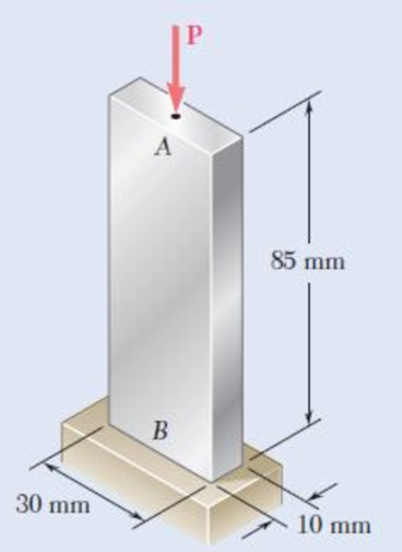
Bar AB is free at its end A and fixed at its base B. Determine the allowable centric load P if the aluminum alloy is (a) 6061-T6, (b) 2014-T6.
Fig. P10.62
Expert Solution & Answer
Want to see the full answer?
Check out a sample textbook solution
Students have asked these similar questions
The frame shown is pinned at points A, B, and C. A single downward vertical force is applied at pin B. Solid
10 mm and are made out of aluminum. You may assume rods AB and
rods AB and BC have diameter d
=
BC are massless.
Determine the largest force Fmar that can be applied to the structure before the onset of buckling in either
rod AB or rod BC is imminent.
212.6
A
Fmax
P
B
Fma
400
number (rtol=0.01, atol=1e-05)
All dimensions in mm
305.3
kN
?
C
The horizontal link BC is 6.35 mm thick, has a width w = 31.8 mm, and is made of steel with ultimate tensile strength equal to 483 MPa. What should be the factor of safety to be used if the structure shown is designed to support a load P = 44.5 kN.
CLASS ACTIVITY 3
DEADLINE: 28 Dec 2021 at 11 pm (will be considered as your attendance)
Determine the largest axial load P that can be safely supported by a flat steel bar consisting of two portions, both 10 mm thick, and respectively
40 and 60 mm wide, connected by fillets of radius r= 8 mm. Assume an allowable normal stress of 165 MPa.
3.4
3.2
D
d
3.0
‚Dld = 2
2.8
1.5
26
1.3
2.4
1.2
K 22
20
16
1.2
10
O 0.02 0.04 0.06 0.05 0.10 0.12 0.14 0.16 0.18 0.20 0.22 0.24 0.26 0.28 0.30
rld
Chapter 10 Solutions
Mechanics of Materials, 7th Edition
Ch. 10.1 - Knowing that the spring at A is of constant k and...Ch. 10.1 - Two rigid bars AC and BC are connected by a pin at...Ch. 10.1 - 10.3 and 10.4 Two rigid bars AC and BC are...Ch. 10.1 - 10.3 and 10.4 Two rigid bars AC and BC are...Ch. 10.1 - The steel rod BC is attached to the rigid bar AB...Ch. 10.1 - The rigid rod AB is attached to a hinge at A and...Ch. 10.1 - The rigid bar AD is attached to two springs of...Ch. 10.1 - A frame consists of four L-shaped members...Ch. 10.1 - Determine the critical load of a pin-ended steel...Ch. 10.1 - Determine the critical load of a pin-ended wooden...
Ch. 10.1 - A column of effective length L can be made by...Ch. 10.1 - A compression member of 1.5-m effective length...Ch. 10.1 - Determine the radius of the round strut so that...Ch. 10.1 - Determine (a) the critical load for the square...Ch. 10.1 - A column with the cross section shown has a...Ch. 10.1 - A column is made from half of a W360 216...Ch. 10.1 - A column of 22-ft effective length is made by...Ch. 10.1 - A single compression member of 8.2-m effective...Ch. 10.1 - Knowing that P = 5.2 kN, determine the factor of...Ch. 10.1 - Members AB and CD are 30-mm-diameter steel rods,...Ch. 10.1 - The uniform brass bar AB has a rectangular cross...Ch. 10.1 - A 1-in.-square aluminum strut is maintained in the...Ch. 10.1 - A 1-in.-square aluminum strut is maintained in the...Ch. 10.1 - Column ABC has a uniform rectangular cross section...Ch. 10.1 - Column ABC has a uniform rectangular cross section...Ch. 10.1 - Column AB carries a centric load P of magnitude 15...Ch. 10.1 - Each of the five struts shown consists of a solid...Ch. 10.1 - A rigid block of mass m can be supported in each...Ch. 10.2 - An axial load P = 15 kN is applied at point D that...Ch. 10.2 - An axial load P is applied to the 32-mm-diameter...Ch. 10.2 - The line of action of the 310-kN axial load is...Ch. 10.2 - Prob. 32PCh. 10.2 - An axial load P is applied to the 32-mm-square...Ch. 10.2 - Prob. 34PCh. 10.2 - Prob. 35PCh. 10.2 - Prob. 36PCh. 10.2 - Solve Prob. 10.36, assuming that the axial load P...Ch. 10.2 - The line of action of the axial load P is parallel...Ch. 10.2 - Prob. 39PCh. 10.2 - Prob. 40PCh. 10.2 - The steel bar AB has a 3838-in. square cross...Ch. 10.2 - For the bar of Prob. 10.41, determine the required...Ch. 10.2 - A 3.5-m-long steel tube having the cross section...Ch. 10.2 - Prob. 44PCh. 10.2 - An axial load P is applied to the W8 28...Ch. 10.2 - Prob. 46PCh. 10.2 - A 100-kN axial load P is applied to the W150 18...Ch. 10.2 - A 26-kip axial load P is applied to a W6 12...Ch. 10.2 - Prob. 49PCh. 10.2 - Axial loads of magnitude P = 84 kN are applied...Ch. 10.2 - An axial load of magnitude P = 220 kN is applied...Ch. 10.2 - Prob. 52PCh. 10.2 - Prob. 53PCh. 10.2 - Prob. 54PCh. 10.2 - Axial loads of magnitude P = 175 kN are applied...Ch. 10.2 - Prob. 56PCh. 10.3 - Using allowable stress design, determine the...Ch. 10.3 - Prob. 58PCh. 10.3 - Prob. 59PCh. 10.3 - A column having a 3.5-m effective length is made...Ch. 10.3 - Prob. 61PCh. 10.3 - Bar AB is free at its end A and fixed at its base...Ch. 10.3 - Prob. 63PCh. 10.3 - Prob. 64PCh. 10.3 - A compression member of 8.2-ft effective length is...Ch. 10.3 - A compression member of 9-m effective length is...Ch. 10.3 - A column of 6.4-m effective length is obtained by...Ch. 10.3 - A column of 21-ft effective length is obtained by...Ch. 10.3 - Prob. 69PCh. 10.3 - Prob. 70PCh. 10.3 - Prob. 71PCh. 10.3 - Prob. 72PCh. 10.3 - Prob. 73PCh. 10.3 - For a rod made of aluminum alloy 2014-T6, select...Ch. 10.3 - Prob. 75PCh. 10.3 - Prob. 76PCh. 10.3 - A column of 4.6-m effective length must carry a...Ch. 10.3 - A column of 22.5-ft effective length must carry a...Ch. 10.3 - Prob. 79PCh. 10.3 - A centric load P must be supported by the steel...Ch. 10.3 - A square steel tube having the cross section shown...Ch. 10.3 - Prob. 82PCh. 10.3 - Prob. 83PCh. 10.3 - Two 89 64-mm angles are bolted together as shown...Ch. 10.3 - Prob. 85PCh. 10.3 - Prob. 86PCh. 10.3 - Prob. 87PCh. 10.3 - Prob. 88PCh. 10.4 - An eccentric load is applied at a point 22 mm from...Ch. 10.4 - Prob. 90PCh. 10.4 - Prob. 91PCh. 10.4 - Solve Prob. 10.91 using the interaction method and...Ch. 10.4 - A column of 5.5-m effective length is made of the...Ch. 10.4 - Prob. 94PCh. 10.4 - A steel compression member of 9-ft effective...Ch. 10.4 - Prob. 96PCh. 10.4 - Two L4 3 38-in. steel angles are welded together...Ch. 10.4 - Solve Prob. 10.97 using the interaction method...Ch. 10.4 - A rectangular column is made of a grade of sawn...Ch. 10.4 - Prob. 100PCh. 10.4 - Prob. 101PCh. 10.4 - Prob. 102PCh. 10.4 - Prob. 103PCh. 10.4 - Prob. 104PCh. 10.4 - A steel tube of 80-mm outer diameter is to carry a...Ch. 10.4 - Prob. 106PCh. 10.4 - Prob. 107PCh. 10.4 - Prob. 108PCh. 10.4 - Prob. 109PCh. 10.4 - Prob. 110PCh. 10.4 - Prob. 111PCh. 10.4 - Prob. 112PCh. 10.4 - Prob. 113PCh. 10.4 - Prob. 114PCh. 10.4 - Prob. 115PCh. 10.4 - A steel column of 7.2-m effective length is to...Ch. 10 - Determine (a) the critical load for the steel...Ch. 10 - Prob. 118RPCh. 10 - Prob. 119RPCh. 10 - (a) Considering only buckling in the plane of the...Ch. 10 - Member AB consists of a single C130 3 10.4 steel...Ch. 10 - The line of action of the 75-kip axial load is...Ch. 10 - Prob. 123RPCh. 10 - Prob. 124RPCh. 10 - A rectangular column with a 4.4-m effective length...Ch. 10 - Prob. 126RPCh. 10 - Prob. 127RPCh. 10 - Prob. 128RP
Knowledge Booster


Learn more about
Need a deep-dive on the concept behind this application? Look no further. Learn more about this topic, mechanical-engineering and related others by exploring similar questions and additional content below.Similar questions
- A column of 6.7-m effective length is obtained by connecting four L89 x 89 x 9.5-mm steel angles with lacing bars as shown. Using allowable stress design, determine the allowable centric load for the column. Use oy= 345 MPa and E= 200 GPa. Neglect the effect of the lacing bars on the moment of inertia. (Round the final answer to the nearest whole number.) | 89 mm mm The allowable centric load is kN.arrow_forwardA 3 meters long column has a circular cross-section of diameter 3 cm. Taking the factor of safety as 3. Determine the safe load for the end condition one end is fixed and other end is hinged. Take E = 210 x 10³MPa. O a. 6225.2 kN O b. 6.2 kN O c. 18675.63 N o d. 18.7 kNarrow_forwardDetermine if the following column is long or short, and then determine the critical load on a steel column having a rectangular cross-section, 12mm by 18mm and length of 250 mm. it is fixed on both ends and made from a steel that has the following properties: E=209 Gpa and Sy=290 Mpa. What is the Slenderness ratio, The Cc, The long or short column, The critical load.arrow_forward
- 1. The A-36 stee (Fy= 250 MPa) W 200 x 46 member shown in Fig. is to be used as a pin- w connected column. Determine the largest axial load it can support before it either begins to buckle or the steel yields. :4 m 主arrow_forwardUsing the aluminum alloy 2014-T6, determine the largest allowable length of the aluminum bar AB for a centric load P of magnitude (a) 150 kN, (b) 90 kN, (c) 25 kNarrow_forwardThe 2014-T6 aluminum rod AC is reinforced with the firmly bonded A992 steel tube BC. (Figure 1) When no load is applied to the assembly, the gap between end C and the rigid support is 0.5 mm. Part A Determine the support reaction at C when an axial force of P= 395 kN is applied. Express your answer to three significant figures and include appropriate units. HA Fc = Value Units Submit Request Answer Figure 1 of 1 Part B D Determine the support reaction at D when an axial force of P = 395 kN is applied. 400 mm Express your answer to three significant figures and include appropriate units. B ? A 992 steel 800 mm 50 mm Fp = Value Units a a 25 mm 2014-T6aluminum alloy Section a-a Submit Request Answerarrow_forward
- The distributed load is supported by two pin-connected columns, each having a solid circular cross- section. If AB is made up of aluminum and CD of steel, determine the required diameter of each column so that both will buckle at the same time. (Esteel = 200 GPa, Sy,steel = 250 MPa, Eal = 70 GPa and Sy,al = 100 MPa). 18 kN/m 3 m 0.75 m 0.75 marrow_forwardA 16-ft-long column that is effectively pin-supported at both ends can be made by gluing together three identical 1.5" x 4.5" planks in either of the two configurations shown. Determine the Euler critical load for each configuration. The planks are 4.5 in. Douglas fir (E = 1900 ksi). - - 1.5 in. (a) (b)arrow_forward12. A% in. -diameter rod made of the same material as rods AC and AD in the truss shown was tested to failure and an ultimate load of 29 kips was recorded. Using a factor of safety of 3.0, determine the required diameter (a) of rod AC, (b) of rod AD. 5 ft C 10 ft e -10 ft 10 kips 10 kipsarrow_forward
- Q.9 For which one of the following columns, 47 EI Euler's buckling load A Column with both ends hinged Column with one end fixed and other В end free C Column with both ends fixed Column with one end fixed and other D hingedarrow_forwardA long solid steel bar of uniform 1.25 in diameter has a 0.375 in diameter hole at its center with its axis perpendicular to the length of the shaft. A tensile load of 108,000 lb is applied longitudinally to the bar. Determine the probable material that can be used for this load for a factor of safety of 5arrow_forwardProblem 4.54 I Review Part A The 2014-T6 aluminum rod AC is reinforced with the firmly bonded A992 steel tube BC. (Figure 1) When no load is applied to the assembly, the gap between end C and the rigid support is 0.5 mm. Determine the support reaction at C when an axial force of P = 465 kN is applied. Express your answer to three significant figures and include appropriate units. Fc = Value Units Submit Request Answer Part B Determine the support reaction at D when an axial force of P = 465 kN is applied. Express your answer to three significant figures and include appropriate units. HA FD = Value Units Figure 1 of 1 Submit Request Answer 400 mm Provide Feedback B A 992 steel 800 mm 50 mm 25 mm 2014-T6aluminum alloy Seation a-aarrow_forward
arrow_back_ios
SEE MORE QUESTIONS
arrow_forward_ios
Recommended textbooks for you
 Elements Of ElectromagneticsMechanical EngineeringISBN:9780190698614Author:Sadiku, Matthew N. O.Publisher:Oxford University Press
 Mechanics of Materials (10th Edition)Mechanical EngineeringISBN:9780134319650Author:Russell C. HibbelerPublisher:PEARSON
 Thermodynamics: An Engineering ApproachMechanical EngineeringISBN:9781259822674Author:Yunus A. Cengel Dr., Michael A. BolesPublisher:McGraw-Hill Education
 Control Systems EngineeringMechanical EngineeringISBN:9781118170519Author:Norman S. NisePublisher:WILEY
 Mechanics of Materials (MindTap Course List)Mechanical EngineeringISBN:9781337093347Author:Barry J. Goodno, James M. GerePublisher:Cengage Learning
 Engineering Mechanics: StaticsMechanical EngineeringISBN:9781118807330Author:James L. Meriam, L. G. Kraige, J. N. BoltonPublisher:WILEY
Elements Of Electromagnetics
Mechanical Engineering
ISBN:9780190698614
Author:Sadiku, Matthew N. O.
Publisher:Oxford University Press
Mechanics of Materials (10th Edition)
Mechanical Engineering
ISBN:9780134319650
Author:Russell C. Hibbeler
Publisher:PEARSON
Thermodynamics: An Engineering Approach
Mechanical Engineering
ISBN:9781259822674
Author:Yunus A. Cengel Dr., Michael A. Boles
Publisher:McGraw-Hill Education
Control Systems Engineering
Mechanical Engineering
ISBN:9781118170519
Author:Norman S. Nise
Publisher:WILEY
Mechanics of Materials (MindTap Course List)
Mechanical Engineering
ISBN:9781337093347
Author:Barry J. Goodno, James M. Gere
Publisher:Cengage Learning
Engineering Mechanics: Statics
Mechanical Engineering
ISBN:9781118807330
Author:James L. Meriam, L. G. Kraige, J. N. Bolton
Publisher:WILEY
Column buckling; Author: Amber Book;https://www.youtube.com/watch?v=AvvaCi_Nn94;License: Standard Youtube License