
Concept explainers
Videos
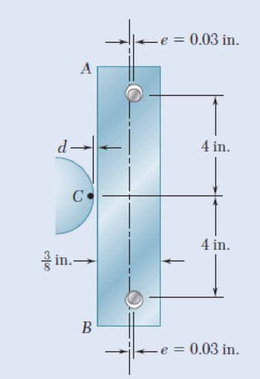
For the bar of Prob. 10.41, determine the required distance d for which the bar will just make contact with point C when the temperature increases by 120 °F.
10.41 The steel bar AB has a
Fig. P10.41
Want to see the full answer?
Check out a sample textbook solution
Chapter 10 Solutions
Mechanics of Materials, 7th Edition


- PROBLEM 10.21 10.21 The uniform brass bar AB has a rectangular cross section and is supported by pins and brackets as shown. Each end of the bar can rotate freely about a horizontal axis through the pin, but rotation about a vertical axis is prevented by the brackets. (a) Determine the ratio bld for which the factor of safety is the same about the horizontal and vertical axes. (b) Determine the factor of safety if P = 8 L = 2m, d = 38 mm, and E = 105 GPa. B kN,arrow_forwardThe uniform brass bar AB has a rectangular cross section and is supported by pins and brackets as shown. Each end of the bar can rotate freely about a horizontal axis through the pin, but rotation about a vertical axis is prevented by the brackets. (a) Determine the ratio b/d for which the factor of safety is the same about the horizontal and vertical axes. (b) Determine the factor of safety if P= 1.8 kips, L = 7ft,d=1.5in,and E=29 X 10° psi.arrow_forward1. A steel plate 5 /16 in. thick is embedded in a horizontal concrete slab and is used to anchor a high- strength vertical cable as shown. The diameter of the hole in the plate is 3 /4 in., the ultỉmate strength of the steel used is 36 ksi, and the ultimate bonding stress between plate and concrete is 300 psi. Knowing that a factor of safety of 3.60 is desired when P=2.5 kips, determine (a) the required width a of the plate, (b) the minimum depth b to which a plate of that width should be embedded in the concrete slab. (Neglect the normal stresses between the concrete and the bottom edge of the plate.arrow_forward
- Two cylindrical rods, one of steel and the other of brass, are joined at C and restrained by rigid supports at A and E. The steel rod has a length of 300 mm while the brass rod has a length of 200 mm. The diameters of the rods are shown in the figure below. A force of 60 kN is applied at point B of the steel segment. For the loading shown and knowing that modulus of elasticity values for steel and brass are respectively Es = 200 GPa and Eb = 105 GPa, determine a.) The reactions at A and E: RA and RE. b.) The deflection of point C from its original location. how to doarrow_forwardTwo gage marks are placed exactly 10 in. apart on a 1⁄2-in.-diameter aluminum rod with E = 10.1 x 10⁶ psi and an ultimate strength of 16 ksi. Knowing that the distance between the gage marks is 10.009 in. after a load isapplied, determine (a) the stress in the rod, (b) the factor of safety, (c) the corresponding normal stress in thewire.arrow_forwardHelp me i need solve this _II_ A steel plate 10 mm thick is embedded in a horizontal concrete slab and is used to anchor high strength vertical cable as shown. The diameter of the hole in the plate is 24 mm. the ultimate strength of the steel used is 250 MPa. and the ultimate bonding stress between plate and concrete is 2.1 MPa. Knowing that a factor of safety of 3.60 is desired when P = 18 kN. Determine: a) the required width a of the plate. b) the minimum depth bb to which a plate of that width should be embedded in the concrete slab. (Neglect the normal stresses between the concrete and the lower end of the plate.)arrow_forward
- The steel bar AB has a x-in.square cross section and is held by pins that are a fixed distance apart and are located at a distance e = 0.034 in. from the geometric axis of the bar. Determine the required distance d for which the bar will just make contact with point C when the temperature increases by 120°F. Use E= 29 × 106 psi and a coefficient of thermal expansion a = 6.5 × 10⁻⁶/°F. Use a simple approximation by ignoring the eccentricity during the thermal part of your calculation. (Round the final answer to four decimal places.) in.- B The distance dis 4 in. 4 in. in.arrow_forwardQuestion 2 The rods BE and CD are made from steel (E=200 GPa), and each have a diameter, 0. The ends of the rods are threaded with a pitch, p. The nuts at B and C are initially finger tightened such that they barely touch rigid member ABC. If the nut at C is then tightened by one full turn, determine: (a) the tension in rods BE and CD (b) the distance, uc, that point C on the rigid member ABC moves. Assume a=150 mm, b= 100 mm, c= 2 m, d= 3 m, =16 mm, and p=2.5 mm. OA a В E D C с d Drawing is not to scale.arrow_forward250 mm 400 mm 1.53 Each of the two vertical links CF connecting the two horizontal members AD and EG has a 10 x 40-mm uniform rectangular cross section and is made of a steel with an ultimate strength in tension of 400 MPa, while each of the pins at C and F has a 20-mm diameter and are made of a steel with an ultimate strength in shear of 150 MPa. Determine the overall factor of safety for the links CF and the pins connecting them to the horizontal members. A 250 mm D E F 24 kNarrow_forward
- An aluminum plate (E= 74 GPa, ν= 0.33) is subjected to a centric axial load that causes a normal stress σ. Knowing that, before loading, a line of slope 2:1 is scribed on the plate, determine the slope of the line when σ=125 MPa.arrow_forwardA line of slope 4:10 has been scribed on a cold-rolled yellow-brass plate, 6 in. wide and 1414 in. thick. Knowing that E = 15 × 106 psi and ν = 0.34, determine the slope of the line when the plate is subjected to a 50-kip centric axial load P as shown. The slope of the line is .arrow_forwardEach of the two vertical links CF connecting the two horizontal members AD and EG has a 10x40-mm uniform rectangular cross section and is made of a steel with an ultimate strength in tension of 400 MPa,while each of the pins at C and F has a 20-mm diameter and is made of a steel with an ultimate strength in shear of 150 MPa. Determine the overall factor of safety for the links CF and the pins connecting them to the horizontal members.arrow_forward
 Elements Of ElectromagneticsMechanical EngineeringISBN:9780190698614Author:Sadiku, Matthew N. O.Publisher:Oxford University Press
 Mechanics of Materials (10th Edition)Mechanical EngineeringISBN:9780134319650Author:Russell C. HibbelerPublisher:PEARSON
 Thermodynamics: An Engineering ApproachMechanical EngineeringISBN:9781259822674Author:Yunus A. Cengel Dr., Michael A. BolesPublisher:McGraw-Hill Education
 Control Systems EngineeringMechanical EngineeringISBN:9781118170519Author:Norman S. NisePublisher:WILEY
 Mechanics of Materials (MindTap Course List)Mechanical EngineeringISBN:9781337093347Author:Barry J. Goodno, James M. GerePublisher:Cengage Learning
 Engineering Mechanics: StaticsMechanical EngineeringISBN:9781118807330Author:James L. Meriam, L. G. Kraige, J. N. BoltonPublisher:WILEY