
Mechanics of Materials, 7th Edition
7th Edition
ISBN: 9780073398235
Author: Ferdinand P. Beer, E. Russell Johnston Jr., John T. DeWolf, David F. Mazurek
Publisher: McGraw-Hill Education
expand_more
expand_more
format_list_bulleted
Concept explainers
Videos
Textbook Question
Chapter 10.1, Problem 23P
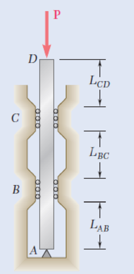
A 1-in.-square aluminum strut is maintained in the position shown by a pin support at A and by sets of rollers at B and C that prevent rotation of the strut in the plane of the figure. Knowing that LAB = 3 ft, LBC = 4 ft , and LCD = 1 ft, determine the allowable load P using a factor of safety with respect to buckling of 3.2. Consider only buckling in the plane of the figure and use E = 10.4 × 10⁶ psi.
Fig. P10.22 and P10.23
Expert Solution & Answer
Want to see the full answer?
Check out a sample textbook solution
Students have asked these similar questions
Link 3 shown acts as a brace to support the
270-lb load. For buckling in the plane of
the figure, the link may be regarded as
pinned at both ends; for out of plane
buckling both ends are fixed. If the link is
to be made of CD 1020 steel and is 1-in
wide, and considering only out-of-plane
buckling, determine a suitable standard
thickness using a design factor of 3.
F= 270 lbf
3 ft
60
SOLUTION:
Axial loads are applied with rigid bearing plates to the solid cylindrical rods shown. If F₁ = 31 kips, F₂ = 11 kips, F3 = 22 kips, and F4 = 36
kips, determine the absolute value of the axial load in rod (2).
F
A
F₂ (1) F₂
B
F3
C
(3)
D
O 16 kips
O 12 kips
O 7 kips
O 9 kips
O 22 kips
The rigid bars AB and CD shown in Fig. are supported by pins at A
and C and the two rods. Determine the maximum force P that can
be applied if the movement of (P) is limited to 10 mm. Neglect the
wieghts of all members.
Aluminum
L = 2 m
A = 500 mm²
E = 70 GPa
A
3 m
3 m
3 m
0
P
3m
B
Steel
L= 2 m
A = 300 mm²
E = 200 GPa
D
P = 153 KN
P = 133 KN
P = 113 KN
P = 103 kN O
Chapter 10 Solutions
Mechanics of Materials, 7th Edition
Ch. 10.1 - Knowing that the spring at A is of constant k and...Ch. 10.1 - Two rigid bars AC and BC are connected by a pin at...Ch. 10.1 - 10.3 and 10.4 Two rigid bars AC and BC are...Ch. 10.1 - 10.3 and 10.4 Two rigid bars AC and BC are...Ch. 10.1 - The steel rod BC is attached to the rigid bar AB...Ch. 10.1 - The rigid rod AB is attached to a hinge at A and...Ch. 10.1 - The rigid bar AD is attached to two springs of...Ch. 10.1 - A frame consists of four L-shaped members...Ch. 10.1 - Determine the critical load of a pin-ended steel...Ch. 10.1 - Determine the critical load of a pin-ended wooden...
Ch. 10.1 - A column of effective length L can be made by...Ch. 10.1 - A compression member of 1.5-m effective length...Ch. 10.1 - Determine the radius of the round strut so that...Ch. 10.1 - Determine (a) the critical load for the square...Ch. 10.1 - A column with the cross section shown has a...Ch. 10.1 - A column is made from half of a W360 216...Ch. 10.1 - A column of 22-ft effective length is made by...Ch. 10.1 - A single compression member of 8.2-m effective...Ch. 10.1 - Knowing that P = 5.2 kN, determine the factor of...Ch. 10.1 - Members AB and CD are 30-mm-diameter steel rods,...Ch. 10.1 - The uniform brass bar AB has a rectangular cross...Ch. 10.1 - A 1-in.-square aluminum strut is maintained in the...Ch. 10.1 - A 1-in.-square aluminum strut is maintained in the...Ch. 10.1 - Column ABC has a uniform rectangular cross section...Ch. 10.1 - Column ABC has a uniform rectangular cross section...Ch. 10.1 - Column AB carries a centric load P of magnitude 15...Ch. 10.1 - Each of the five struts shown consists of a solid...Ch. 10.1 - A rigid block of mass m can be supported in each...Ch. 10.2 - An axial load P = 15 kN is applied at point D that...Ch. 10.2 - An axial load P is applied to the 32-mm-diameter...Ch. 10.2 - The line of action of the 310-kN axial load is...Ch. 10.2 - Prob. 32PCh. 10.2 - An axial load P is applied to the 32-mm-square...Ch. 10.2 - Prob. 34PCh. 10.2 - Prob. 35PCh. 10.2 - Prob. 36PCh. 10.2 - Solve Prob. 10.36, assuming that the axial load P...Ch. 10.2 - The line of action of the axial load P is parallel...Ch. 10.2 - Prob. 39PCh. 10.2 - Prob. 40PCh. 10.2 - The steel bar AB has a 3838-in. square cross...Ch. 10.2 - For the bar of Prob. 10.41, determine the required...Ch. 10.2 - A 3.5-m-long steel tube having the cross section...Ch. 10.2 - Prob. 44PCh. 10.2 - An axial load P is applied to the W8 28...Ch. 10.2 - Prob. 46PCh. 10.2 - A 100-kN axial load P is applied to the W150 18...Ch. 10.2 - A 26-kip axial load P is applied to a W6 12...Ch. 10.2 - Prob. 49PCh. 10.2 - Axial loads of magnitude P = 84 kN are applied...Ch. 10.2 - An axial load of magnitude P = 220 kN is applied...Ch. 10.2 - Prob. 52PCh. 10.2 - Prob. 53PCh. 10.2 - Prob. 54PCh. 10.2 - Axial loads of magnitude P = 175 kN are applied...Ch. 10.2 - Prob. 56PCh. 10.3 - Using allowable stress design, determine the...Ch. 10.3 - Prob. 58PCh. 10.3 - Prob. 59PCh. 10.3 - A column having a 3.5-m effective length is made...Ch. 10.3 - Prob. 61PCh. 10.3 - Bar AB is free at its end A and fixed at its base...Ch. 10.3 - Prob. 63PCh. 10.3 - Prob. 64PCh. 10.3 - A compression member of 8.2-ft effective length is...Ch. 10.3 - A compression member of 9-m effective length is...Ch. 10.3 - A column of 6.4-m effective length is obtained by...Ch. 10.3 - A column of 21-ft effective length is obtained by...Ch. 10.3 - Prob. 69PCh. 10.3 - Prob. 70PCh. 10.3 - Prob. 71PCh. 10.3 - Prob. 72PCh. 10.3 - Prob. 73PCh. 10.3 - For a rod made of aluminum alloy 2014-T6, select...Ch. 10.3 - Prob. 75PCh. 10.3 - Prob. 76PCh. 10.3 - A column of 4.6-m effective length must carry a...Ch. 10.3 - A column of 22.5-ft effective length must carry a...Ch. 10.3 - Prob. 79PCh. 10.3 - A centric load P must be supported by the steel...Ch. 10.3 - A square steel tube having the cross section shown...Ch. 10.3 - Prob. 82PCh. 10.3 - Prob. 83PCh. 10.3 - Two 89 64-mm angles are bolted together as shown...Ch. 10.3 - Prob. 85PCh. 10.3 - Prob. 86PCh. 10.3 - Prob. 87PCh. 10.3 - Prob. 88PCh. 10.4 - An eccentric load is applied at a point 22 mm from...Ch. 10.4 - Prob. 90PCh. 10.4 - Prob. 91PCh. 10.4 - Solve Prob. 10.91 using the interaction method and...Ch. 10.4 - A column of 5.5-m effective length is made of the...Ch. 10.4 - Prob. 94PCh. 10.4 - A steel compression member of 9-ft effective...Ch. 10.4 - Prob. 96PCh. 10.4 - Two L4 3 38-in. steel angles are welded together...Ch. 10.4 - Solve Prob. 10.97 using the interaction method...Ch. 10.4 - A rectangular column is made of a grade of sawn...Ch. 10.4 - Prob. 100PCh. 10.4 - Prob. 101PCh. 10.4 - Prob. 102PCh. 10.4 - Prob. 103PCh. 10.4 - Prob. 104PCh. 10.4 - A steel tube of 80-mm outer diameter is to carry a...Ch. 10.4 - Prob. 106PCh. 10.4 - Prob. 107PCh. 10.4 - Prob. 108PCh. 10.4 - Prob. 109PCh. 10.4 - Prob. 110PCh. 10.4 - Prob. 111PCh. 10.4 - Prob. 112PCh. 10.4 - Prob. 113PCh. 10.4 - Prob. 114PCh. 10.4 - Prob. 115PCh. 10.4 - A steel column of 7.2-m effective length is to...Ch. 10 - Determine (a) the critical load for the steel...Ch. 10 - Prob. 118RPCh. 10 - Prob. 119RPCh. 10 - (a) Considering only buckling in the plane of the...Ch. 10 - Member AB consists of a single C130 3 10.4 steel...Ch. 10 - The line of action of the 75-kip axial load is...Ch. 10 - Prob. 123RPCh. 10 - Prob. 124RPCh. 10 - A rectangular column with a 4.4-m effective length...Ch. 10 - Prob. 126RPCh. 10 - Prob. 127RPCh. 10 - Prob. 128RP
Knowledge Booster


Learn more about
Need a deep-dive on the concept behind this application? Look no further. Learn more about this topic, mechanical-engineering and related others by exploring similar questions and additional content below.Similar questions
- 7. In the wedge shown in the figure. Determine the largest angle that will cause the wedge to be self locking whatever the value of force P may be. Neglect the weight of the wedge. Hg = 0.3 P 0 Parrow_forward7 ft 5 ft The assembly shown above includes column AB, which has the following properties: Pinned (top and bottom) for buckling about x-axis Free at top and fixed at bottom for buckling about y-axis Circular cross-section with 8-inch diameter E = 10000 ksi Which of the following is closest to the critical buckling force of column AB? O Per = 269 kip O Per = 1080 kip O Per = 538 kip O Per = 135 kiparrow_forwardThe bell-crank mechanism is in equilibrium for an applied load of P = 24 kN. Assume that a = 300 mm, b = 235 mm, and θ = 55°. The pin at B has a diameter of d = 22 mm, and the bell crank has a thickness of t = 7 mm. Calculate the bearing stress in the bell crank at pin B.arrow_forward
- The bell-crank mechanism shown below is supported by a single-shear pin connection at B and a roller support at C. A load P acts at an angle of θ=40° at joint A. The pin at B has a diameter of 0.375 in, and the bell crank has a thickness of 0.188 in. The ultimate shear strenght of the pin material is 28 ksi, and the ultimate bearing strenght of the crank material is 52 ksi. A minimum factor of safety of 3.0 with respect to shear and bearing is required. Assume that a = 9.0 in. and b =5.0 in. What is the maximum load P that may be applied at joint A of the bell crank?arrow_forwardG2/ The bar AB is considered to be absolutely rigid and is horizontal before the load of &8000 N is applied. The conneetion at C is a pin, and AB is supported by the bronze rod EA and the steel rod FB. The length of EA is 4m and FB is 3 m. Neglect any possibility of lateral buckling and the weights of all bars „Calculate the stresses in each rod. For bronze E=100 GPa, A=50 mm2 for steel E=200 GPa, A=30 mm2 Steel L=3m 10m 5m Bronze L=4m 8000 Narrow_forwardThe rigid beam shown is supported by a pin at A and two steel rods each of diameter 16 mm. If P = 30 kN, determine the tensile forces PBe & Pcr in rods BE and CF, respectively. For steel, E = 200 GRa: F 2.0 m E P = 30 kN 2.5 m B -3 m- -3 m-arrow_forward
- An aluminum column with a length of L and a rectangular cross-section has a fixed end B and supports a centric load at A. Two smooth and rounded fixed plates restrain end a from moving in one of the vertical planes of symmetry of the column but allow it to move in the other plane. (a) Determine the ratio a/b of the two sides of the cross section corresponding to the most efficient design against buckling. (b) Design the most efficient cross section for the column, knowing that L = 20in., E=10.1 x 10^6 psi, P = 5kips, and a factor of safety of 2.5 is required. Consider Sample Problem 10.1. Solve the same problem, but this time replace the pinned boundary condition on top with a fixed boundary condition. You otherwise leave all other aspects of the problem unchanged. Be sure to answer both Part a and Part b. As careful observation, please do keep in mind that two things happen: First, on top, the pinned boundary condition in one place is replaced by the fixed boundary condition in that…arrow_forwardQ2. The pin-connected frame is subjected to the force Fas shown. The dimensions are 4-4.0 ft, - 2.6 ft. and -3.9 ft. Member BC is made of steel (E- 29000 ksi), and has rectangular cross-section, with b- 13 in. and h=4.1 in. The supports at B and Cact as pins for x-x axis buckling and as fixed supports for y yaxis buckling. Determine the greatest load F(in the unit of kip) the beam will support without causing member BC to buckle. Please pay attention: the numbers may change since they are randomized. Your answer must include 2 places after the decimal point. Your Answer:arrow_forwardAn aluminum column with a length of L and a rectangular cross-section has a fixed end B and supports a centric load at A. Two smooth and rounded fixed plates restrain end a from moving in one of the vertical planes of symmetry of the column but allow it to move in the other plane. (a) Determine the ratio a/b of the two sides of the cross section corresponding to the most efficient design against buckling. (b) Design the most efficient cross section for the column, knowing that L = 20in., E=10.1 x 10^6 psi, P = 5kips, and a factor of safety of 2.5 is required. Now, replace the pinned boundary condition on top with a fixed boundary condition. You otherwise leave all other aspects of the problem unchanged.arrow_forward
- Q#3. An aluminium strut 16 ft long has a rectangular cross section 2 in by 3.5 in. A bolt through each end secure the strut in such a way that is acts as hinged column about an axis perpendicular to 3.5 in dimension; and as fixed column about an axis perpendicular to 2 in dimension. Determine the safe central load with a factor of safety of 2 and E= 10300000 psi. Also discuss in detail about the governing column capacity and reasons behind it.arrow_forwardThe truss below is subject to the loads as shown. All of the members are attached at plates and can be treated as pin connected. The truss is attached to the ground at a pin joint at G and a roller at D. The applied load H is 357 N. The applied load J is 321 N. What is the internal resultant normal force in member AE in N? (tension is positive, compression is negative) E F G A 3 m B Η. 3 m 3 m D 5 marrow_forwardIn the steel structure showm in the figure, a 6 mm diameter pin is used at C and 10 mm diameter pins are used at B and D. The shear stress limit is 150 MPa in all connections, and the normal stress is 400 MPa at bar BD. Knowing that a factor of safety of 3.0 is desired, determine the largest load P that can be applied at A. Note that bar BD is not reinforced around the pin holes. D FRONT VIEW 80mm- 22 mm 5 mm 2kN/m В B SIDE VIEW 210 mm 150 mm P A UPPER VIEWarrow_forward
arrow_back_ios
SEE MORE QUESTIONS
arrow_forward_ios
Recommended textbooks for you
 Elements Of ElectromagneticsMechanical EngineeringISBN:9780190698614Author:Sadiku, Matthew N. O.Publisher:Oxford University Press
 Mechanics of Materials (10th Edition)Mechanical EngineeringISBN:9780134319650Author:Russell C. HibbelerPublisher:PEARSON
 Thermodynamics: An Engineering ApproachMechanical EngineeringISBN:9781259822674Author:Yunus A. Cengel Dr., Michael A. BolesPublisher:McGraw-Hill Education
 Control Systems EngineeringMechanical EngineeringISBN:9781118170519Author:Norman S. NisePublisher:WILEY
 Mechanics of Materials (MindTap Course List)Mechanical EngineeringISBN:9781337093347Author:Barry J. Goodno, James M. GerePublisher:Cengage Learning
 Engineering Mechanics: StaticsMechanical EngineeringISBN:9781118807330Author:James L. Meriam, L. G. Kraige, J. N. BoltonPublisher:WILEY
Elements Of Electromagnetics
Mechanical Engineering
ISBN:9780190698614
Author:Sadiku, Matthew N. O.
Publisher:Oxford University Press
Mechanics of Materials (10th Edition)
Mechanical Engineering
ISBN:9780134319650
Author:Russell C. Hibbeler
Publisher:PEARSON
Thermodynamics: An Engineering Approach
Mechanical Engineering
ISBN:9781259822674
Author:Yunus A. Cengel Dr., Michael A. Boles
Publisher:McGraw-Hill Education
Control Systems Engineering
Mechanical Engineering
ISBN:9781118170519
Author:Norman S. Nise
Publisher:WILEY
Mechanics of Materials (MindTap Course List)
Mechanical Engineering
ISBN:9781337093347
Author:Barry J. Goodno, James M. Gere
Publisher:Cengage Learning
Engineering Mechanics: Statics
Mechanical Engineering
ISBN:9781118807330
Author:James L. Meriam, L. G. Kraige, J. N. Bolton
Publisher:WILEY
Column buckling; Author: Amber Book;https://www.youtube.com/watch?v=AvvaCi_Nn94;License: Standard Youtube License