
Mechanics of Materials, 7th Edition
7th Edition
ISBN: 9780073398235
Author: Ferdinand P. Beer, E. Russell Johnston Jr., John T. DeWolf, David F. Mazurek
Publisher: McGraw-Hill Education
expand_more
expand_more
format_list_bulleted
Concept explainers
Videos
Textbook Question
Chapter 10.2, Problem 38P
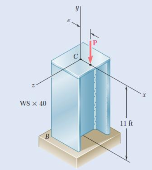
The line of action of the axial load P is parallel to the geometric axis of the column AB and intersects the x axis at x = 0.8 in. Using E = 29 3 106 psi, determine (a) the load P for which the horizontal deflection at the end C is 0.5 in., (b) the corresponding maximum stress in the column.
Fig. P10.38
Expert Solution & Answer
Want to see the full answer?
Check out a sample textbook solution
Students have asked these similar questions
The rigid beam BC is supported by rods (1) and (2). The cross-sectional area of rod (1) is 7 mm2. The cross-sectional area of rod (2) is 18 mm2. For a uniformly distributed load of w = 2.7 kN/m, determine the length a so that the normal stress is the same in each rod. Assume L = 5.65 m.
An Euler column is safely to carry a compressive load of 60 kN. The cross sectional
area is A=1452 mm². The radii of gyrations are rx= 14.75 mm and ry= 41.6 mm.
Knowing E= 200 GPa and that the ends are simply-supported all around, determine the
maximum allowable length L. Use F.S.= 1.92.
P=60x10³ N
P
The rigid beam BC is supported by rods (1) and (2). The cross-sectional area of rod (1) is 11 mm². The cross-sectional area of rod (2) is
15 mm². For a uniformly distributed load of w = 3.2 kN/m, determine the length a so that the normal stress is the same in each rod.
Assume L = 5.60 m.
A
(1)
B
Answer: a =
i
L
a
D
(2)
m
Chapter 10 Solutions
Mechanics of Materials, 7th Edition
Ch. 10.1 - Knowing that the spring at A is of constant k and...Ch. 10.1 - Two rigid bars AC and BC are connected by a pin at...Ch. 10.1 - 10.3 and 10.4 Two rigid bars AC and BC are...Ch. 10.1 - 10.3 and 10.4 Two rigid bars AC and BC are...Ch. 10.1 - The steel rod BC is attached to the rigid bar AB...Ch. 10.1 - The rigid rod AB is attached to a hinge at A and...Ch. 10.1 - The rigid bar AD is attached to two springs of...Ch. 10.1 - A frame consists of four L-shaped members...Ch. 10.1 - Determine the critical load of a pin-ended steel...Ch. 10.1 - Determine the critical load of a pin-ended wooden...
Ch. 10.1 - A column of effective length L can be made by...Ch. 10.1 - A compression member of 1.5-m effective length...Ch. 10.1 - Determine the radius of the round strut so that...Ch. 10.1 - Determine (a) the critical load for the square...Ch. 10.1 - A column with the cross section shown has a...Ch. 10.1 - A column is made from half of a W360 216...Ch. 10.1 - A column of 22-ft effective length is made by...Ch. 10.1 - A single compression member of 8.2-m effective...Ch. 10.1 - Knowing that P = 5.2 kN, determine the factor of...Ch. 10.1 - Members AB and CD are 30-mm-diameter steel rods,...Ch. 10.1 - The uniform brass bar AB has a rectangular cross...Ch. 10.1 - A 1-in.-square aluminum strut is maintained in the...Ch. 10.1 - A 1-in.-square aluminum strut is maintained in the...Ch. 10.1 - Column ABC has a uniform rectangular cross section...Ch. 10.1 - Column ABC has a uniform rectangular cross section...Ch. 10.1 - Column AB carries a centric load P of magnitude 15...Ch. 10.1 - Each of the five struts shown consists of a solid...Ch. 10.1 - A rigid block of mass m can be supported in each...Ch. 10.2 - An axial load P = 15 kN is applied at point D that...Ch. 10.2 - An axial load P is applied to the 32-mm-diameter...Ch. 10.2 - The line of action of the 310-kN axial load is...Ch. 10.2 - Prob. 32PCh. 10.2 - An axial load P is applied to the 32-mm-square...Ch. 10.2 - Prob. 34PCh. 10.2 - Prob. 35PCh. 10.2 - Prob. 36PCh. 10.2 - Solve Prob. 10.36, assuming that the axial load P...Ch. 10.2 - The line of action of the axial load P is parallel...Ch. 10.2 - Prob. 39PCh. 10.2 - Prob. 40PCh. 10.2 - The steel bar AB has a 3838-in. square cross...Ch. 10.2 - For the bar of Prob. 10.41, determine the required...Ch. 10.2 - A 3.5-m-long steel tube having the cross section...Ch. 10.2 - Prob. 44PCh. 10.2 - An axial load P is applied to the W8 28...Ch. 10.2 - Prob. 46PCh. 10.2 - A 100-kN axial load P is applied to the W150 18...Ch. 10.2 - A 26-kip axial load P is applied to a W6 12...Ch. 10.2 - Prob. 49PCh. 10.2 - Axial loads of magnitude P = 84 kN are applied...Ch. 10.2 - An axial load of magnitude P = 220 kN is applied...Ch. 10.2 - Prob. 52PCh. 10.2 - Prob. 53PCh. 10.2 - Prob. 54PCh. 10.2 - Axial loads of magnitude P = 175 kN are applied...Ch. 10.2 - Prob. 56PCh. 10.3 - Using allowable stress design, determine the...Ch. 10.3 - Prob. 58PCh. 10.3 - Prob. 59PCh. 10.3 - A column having a 3.5-m effective length is made...Ch. 10.3 - Prob. 61PCh. 10.3 - Bar AB is free at its end A and fixed at its base...Ch. 10.3 - Prob. 63PCh. 10.3 - Prob. 64PCh. 10.3 - A compression member of 8.2-ft effective length is...Ch. 10.3 - A compression member of 9-m effective length is...Ch. 10.3 - A column of 6.4-m effective length is obtained by...Ch. 10.3 - A column of 21-ft effective length is obtained by...Ch. 10.3 - Prob. 69PCh. 10.3 - Prob. 70PCh. 10.3 - Prob. 71PCh. 10.3 - Prob. 72PCh. 10.3 - Prob. 73PCh. 10.3 - For a rod made of aluminum alloy 2014-T6, select...Ch. 10.3 - Prob. 75PCh. 10.3 - Prob. 76PCh. 10.3 - A column of 4.6-m effective length must carry a...Ch. 10.3 - A column of 22.5-ft effective length must carry a...Ch. 10.3 - Prob. 79PCh. 10.3 - A centric load P must be supported by the steel...Ch. 10.3 - A square steel tube having the cross section shown...Ch. 10.3 - Prob. 82PCh. 10.3 - Prob. 83PCh. 10.3 - Two 89 64-mm angles are bolted together as shown...Ch. 10.3 - Prob. 85PCh. 10.3 - Prob. 86PCh. 10.3 - Prob. 87PCh. 10.3 - Prob. 88PCh. 10.4 - An eccentric load is applied at a point 22 mm from...Ch. 10.4 - Prob. 90PCh. 10.4 - Prob. 91PCh. 10.4 - Solve Prob. 10.91 using the interaction method and...Ch. 10.4 - A column of 5.5-m effective length is made of the...Ch. 10.4 - Prob. 94PCh. 10.4 - A steel compression member of 9-ft effective...Ch. 10.4 - Prob. 96PCh. 10.4 - Two L4 3 38-in. steel angles are welded together...Ch. 10.4 - Solve Prob. 10.97 using the interaction method...Ch. 10.4 - A rectangular column is made of a grade of sawn...Ch. 10.4 - Prob. 100PCh. 10.4 - Prob. 101PCh. 10.4 - Prob. 102PCh. 10.4 - Prob. 103PCh. 10.4 - Prob. 104PCh. 10.4 - A steel tube of 80-mm outer diameter is to carry a...Ch. 10.4 - Prob. 106PCh. 10.4 - Prob. 107PCh. 10.4 - Prob. 108PCh. 10.4 - Prob. 109PCh. 10.4 - Prob. 110PCh. 10.4 - Prob. 111PCh. 10.4 - Prob. 112PCh. 10.4 - Prob. 113PCh. 10.4 - Prob. 114PCh. 10.4 - Prob. 115PCh. 10.4 - A steel column of 7.2-m effective length is to...Ch. 10 - Determine (a) the critical load for the steel...Ch. 10 - Prob. 118RPCh. 10 - Prob. 119RPCh. 10 - (a) Considering only buckling in the plane of the...Ch. 10 - Member AB consists of a single C130 3 10.4 steel...Ch. 10 - The line of action of the 75-kip axial load is...Ch. 10 - Prob. 123RPCh. 10 - Prob. 124RPCh. 10 - A rectangular column with a 4.4-m effective length...Ch. 10 - Prob. 126RPCh. 10 - Prob. 127RPCh. 10 - Prob. 128RP
Knowledge Booster


Learn more about
Need a deep-dive on the concept behind this application? Look no further. Learn more about this topic, mechanical-engineering and related others by exploring similar questions and additional content below.Similar questions
- The rigid beam BC is supported by rods (1) and (2). The cross-sectional area of rod (1) is 8 mm². The cross-sectional area of rod (2) is 17 mm². For a uniformly distributed load of w = 2.8 kN/m, determine the length a so that the normal stress is the same in each rod. Assume L = 4.20 m. (1) B Answer: a = i L W E 2arrow_forward2] The I-beam column shown below is to support a normal load of value P. The column has a cross- sectional area of 14,500 mm2. Determine the minimum required dimension a (mm) so that the bearing stress between the base plate and the concrete slab does not exceed 8000 kPa and the average normal stress in the steel column must not exceed 75000 kPa. Assume that b 42 cm. 9.arrow_forwardPortion BC of the rod ABC are made of an aluminum for which E= 70 GPa and portion AB is made of steel for which E = 200 GPa. Given: P = 9 kN, a = 0.6 m, b=0.7 m and the diameter of rod AB is c = 36 mm, (a) Determine the value of Q so that the deflection at A is zero (b) The corresponding deflection of point B 60-mm diameterarrow_forward
- An axial load P is supported by a short W8x40 column of cross-sectional area A=11.7 in? and is distributed to a concrete foundation by a square plate as shown. Knowing that the average normal stress in the column must not exceed 30ksi and that the bearing stress on the concrete foundation must not exceed 3.0 ksi, determine the side "a" of the plate that will provide the most economical and safe design.arrow_forwardQ1. (A). A 25mm square cross-section bar of length 300mm carries an axial compressive load of 50kN. Determine the stress set up in the bar and its change of length when the load is applied. For the bar material E= 200 GN/m². Q2. A beam AB, 1.2 m long, is simply-supported at its ends A and B and carries two concentrated loads, one of 10 kN at C, the other 15 kN at D. Point C is 0.4 m from A, point D is 1 m from A. Draw the S.F. and B.M. diagrams for the beam. Q3. A solid steel shaft (A) of 50 mm diameter rotates at 250 rev/min. Find the greatest power that can be transmitted for a limiting shearing stress of 60 MN/m2 in the steel.arrow_forwardA steel rod of 30 mm diameter is enclosed centrally in a hollow copper tube of external diameter 40 mm and 5 mm thick. The composite bar is then subjected to an axial pull of 45 kN. If the length of the compound rod is 150 mm , and the elasticity moduli are Est = 200 GPa and Ecu = 100 GPa , determine: 1.2.2 The load carried by the rod and that carried by the tubearrow_forward
- PROBLEM 10.15 12 mm A column with the cross section shown has a 4 m effective length. Using a factor of safety equal to 2.8, determine the allowable centric load that can be applied to the column. Use E = 200 GPa. 250 mm 6 mm 12 mm -150 mmarrow_forwardA rectangular column is made of a grade of sawn wood that has an adjusted allowable stress for compression parallel to the grain σC = 8.3 MPa and a modulus of elasticity E = 11.1 GPa. Using the allowable-stress method, determine the largest allowable effective length L that can be used. Take P = 88 kN. (Round the final answer to two decimal places.) The largest allowable effective length L that can be used is m.arrow_forwardThe rigid beam BC is supported by rods (1) and (2). The cross-sectional area of rod (1) is 7 mm2. The cross-sectional area of rod (2) is 18 mm2. For a uniformly distributed load of w = 2.5 kN/m, determine the length a so that the normal stress is the same in each rod. Assume L = 3.10 m. D (1) B |C aarrow_forward
- The length of the 332332 -in.-diameter steel wire CD has been adjusted so that with no load applied, a gap of 116116 in. exists between the end B of the rigid beam ACB and contact point E. Knowing that E = 29 × 106 psi, determine where a 57-lb (w) block should be placed on the beam in order to cause contact between B and E. For contact, x < in.arrow_forwardQ1. The steel rod AC and brass rod CD are rigidly joined at C. The loads acting are P=60 kN and Q=80 kN. Disregarding the weight of the rods, determine the deflection of (a) point C (b) point D. Given E=200 GPa for steel; E=105 GPa for brass. 2 m B D=40 mm D=25 mm D to 2 m 3 marrow_forwardThe rigid beam BC is supported by rods (1) and (2). The cross-sectional area of rod (1) is 9 mm². The cross-sectional area of rod (2) is 14 mm². For a uniformly distributed load of w 4.0 kN/m, determine the length a so that the normal stress is the same in each rod. Assume L = 4.50 m. (1) Answer: a = L W a (2) marrow_forward
arrow_back_ios
SEE MORE QUESTIONS
arrow_forward_ios
Recommended textbooks for you
 Elements Of ElectromagneticsMechanical EngineeringISBN:9780190698614Author:Sadiku, Matthew N. O.Publisher:Oxford University Press
 Mechanics of Materials (10th Edition)Mechanical EngineeringISBN:9780134319650Author:Russell C. HibbelerPublisher:PEARSON
 Thermodynamics: An Engineering ApproachMechanical EngineeringISBN:9781259822674Author:Yunus A. Cengel Dr., Michael A. BolesPublisher:McGraw-Hill Education
 Control Systems EngineeringMechanical EngineeringISBN:9781118170519Author:Norman S. NisePublisher:WILEY
 Mechanics of Materials (MindTap Course List)Mechanical EngineeringISBN:9781337093347Author:Barry J. Goodno, James M. GerePublisher:Cengage Learning
 Engineering Mechanics: StaticsMechanical EngineeringISBN:9781118807330Author:James L. Meriam, L. G. Kraige, J. N. BoltonPublisher:WILEY
Elements Of Electromagnetics
Mechanical Engineering
ISBN:9780190698614
Author:Sadiku, Matthew N. O.
Publisher:Oxford University Press
Mechanics of Materials (10th Edition)
Mechanical Engineering
ISBN:9780134319650
Author:Russell C. Hibbeler
Publisher:PEARSON
Thermodynamics: An Engineering Approach
Mechanical Engineering
ISBN:9781259822674
Author:Yunus A. Cengel Dr., Michael A. Boles
Publisher:McGraw-Hill Education
Control Systems Engineering
Mechanical Engineering
ISBN:9781118170519
Author:Norman S. Nise
Publisher:WILEY
Mechanics of Materials (MindTap Course List)
Mechanical Engineering
ISBN:9781337093347
Author:Barry J. Goodno, James M. Gere
Publisher:Cengage Learning
Engineering Mechanics: Statics
Mechanical Engineering
ISBN:9781118807330
Author:James L. Meriam, L. G. Kraige, J. N. Bolton
Publisher:WILEY
Column buckling; Author: Amber Book;https://www.youtube.com/watch?v=AvvaCi_Nn94;License: Standard Youtube License