
Mechanics of Materials, 7th Edition
7th Edition
ISBN: 9780073398235
Author: Ferdinand P. Beer, E. Russell Johnston Jr., John T. DeWolf, David F. Mazurek
Publisher: McGraw-Hill Education
expand_more
expand_more
format_list_bulleted
Concept explainers
Videos
Textbook Question
Chapter 10.2, Problem 55P
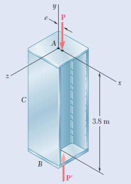
Axial loads of magnitude P = 175 kN are applied parallel to the geometric axis of a W250 × 44.8 rolled-steel column AB and intersect the x axis at a distance e = 12 mm from its geometric axis. Knowing that σY = 250 MPa and E = 200 GPa, determine the factor of safety with respect to yield. (Hint: Since the factor of safety must be applied to the load P, not to the stresses, use Fig. 10.24 to determine PY.)
Fig. 10.55
Expert Solution & Answer
Want to see the full answer?
Check out a sample textbook solution
Students have asked these similar questions
The rigid beam BC is supported by rods (1) and (2). The cross-sectional area of rod (1) is 9 mm². The cross-sectional area of rod (2) is 14
mm². For a uniformly distributed load of w 4.0 kN/m, determine the length a so that the normal stress is the same in each rod.
Assume L = 4.50 m.
(1)
Answer: a =
L
W
a
(2)
m
The rigid beam BC is supported by rods (1) and (2). The cross-sectional area of rod (1) is 10 mm2. The cross-sectional area of rod (2) is 18 mm2. For a uniformly distributed load of w = 2.4 kN/m, determine the length a so that the normal stress is the same in each rod. Assume L = 5.25 m.
A steel wire 30 ft long, hanging vertically, supports a load of 500 lb. Neglecting the
weight of the wire, determine the required diameter if the stress is not to exceed 20
ksi and the total elongation is not to exceed 0.10 in. Assume E = 29 × 10° psi.
0.22 in
0.30 in
0.28 in.
0.20 in.
Chapter 10 Solutions
Mechanics of Materials, 7th Edition
Ch. 10.1 - Knowing that the spring at A is of constant k and...Ch. 10.1 - Two rigid bars AC and BC are connected by a pin at...Ch. 10.1 - 10.3 and 10.4 Two rigid bars AC and BC are...Ch. 10.1 - 10.3 and 10.4 Two rigid bars AC and BC are...Ch. 10.1 - The steel rod BC is attached to the rigid bar AB...Ch. 10.1 - The rigid rod AB is attached to a hinge at A and...Ch. 10.1 - The rigid bar AD is attached to two springs of...Ch. 10.1 - A frame consists of four L-shaped members...Ch. 10.1 - Determine the critical load of a pin-ended steel...Ch. 10.1 - Determine the critical load of a pin-ended wooden...
Ch. 10.1 - A column of effective length L can be made by...Ch. 10.1 - A compression member of 1.5-m effective length...Ch. 10.1 - Determine the radius of the round strut so that...Ch. 10.1 - Determine (a) the critical load for the square...Ch. 10.1 - A column with the cross section shown has a...Ch. 10.1 - A column is made from half of a W360 216...Ch. 10.1 - A column of 22-ft effective length is made by...Ch. 10.1 - A single compression member of 8.2-m effective...Ch. 10.1 - Knowing that P = 5.2 kN, determine the factor of...Ch. 10.1 - Members AB and CD are 30-mm-diameter steel rods,...Ch. 10.1 - The uniform brass bar AB has a rectangular cross...Ch. 10.1 - A 1-in.-square aluminum strut is maintained in the...Ch. 10.1 - A 1-in.-square aluminum strut is maintained in the...Ch. 10.1 - Column ABC has a uniform rectangular cross section...Ch. 10.1 - Column ABC has a uniform rectangular cross section...Ch. 10.1 - Column AB carries a centric load P of magnitude 15...Ch. 10.1 - Each of the five struts shown consists of a solid...Ch. 10.1 - A rigid block of mass m can be supported in each...Ch. 10.2 - An axial load P = 15 kN is applied at point D that...Ch. 10.2 - An axial load P is applied to the 32-mm-diameter...Ch. 10.2 - The line of action of the 310-kN axial load is...Ch. 10.2 - Prob. 32PCh. 10.2 - An axial load P is applied to the 32-mm-square...Ch. 10.2 - Prob. 34PCh. 10.2 - Prob. 35PCh. 10.2 - Prob. 36PCh. 10.2 - Solve Prob. 10.36, assuming that the axial load P...Ch. 10.2 - The line of action of the axial load P is parallel...Ch. 10.2 - Prob. 39PCh. 10.2 - Prob. 40PCh. 10.2 - The steel bar AB has a 3838-in. square cross...Ch. 10.2 - For the bar of Prob. 10.41, determine the required...Ch. 10.2 - A 3.5-m-long steel tube having the cross section...Ch. 10.2 - Prob. 44PCh. 10.2 - An axial load P is applied to the W8 28...Ch. 10.2 - Prob. 46PCh. 10.2 - A 100-kN axial load P is applied to the W150 18...Ch. 10.2 - A 26-kip axial load P is applied to a W6 12...Ch. 10.2 - Prob. 49PCh. 10.2 - Axial loads of magnitude P = 84 kN are applied...Ch. 10.2 - An axial load of magnitude P = 220 kN is applied...Ch. 10.2 - Prob. 52PCh. 10.2 - Prob. 53PCh. 10.2 - Prob. 54PCh. 10.2 - Axial loads of magnitude P = 175 kN are applied...Ch. 10.2 - Prob. 56PCh. 10.3 - Using allowable stress design, determine the...Ch. 10.3 - Prob. 58PCh. 10.3 - Prob. 59PCh. 10.3 - A column having a 3.5-m effective length is made...Ch. 10.3 - Prob. 61PCh. 10.3 - Bar AB is free at its end A and fixed at its base...Ch. 10.3 - Prob. 63PCh. 10.3 - Prob. 64PCh. 10.3 - A compression member of 8.2-ft effective length is...Ch. 10.3 - A compression member of 9-m effective length is...Ch. 10.3 - A column of 6.4-m effective length is obtained by...Ch. 10.3 - A column of 21-ft effective length is obtained by...Ch. 10.3 - Prob. 69PCh. 10.3 - Prob. 70PCh. 10.3 - Prob. 71PCh. 10.3 - Prob. 72PCh. 10.3 - Prob. 73PCh. 10.3 - For a rod made of aluminum alloy 2014-T6, select...Ch. 10.3 - Prob. 75PCh. 10.3 - Prob. 76PCh. 10.3 - A column of 4.6-m effective length must carry a...Ch. 10.3 - A column of 22.5-ft effective length must carry a...Ch. 10.3 - Prob. 79PCh. 10.3 - A centric load P must be supported by the steel...Ch. 10.3 - A square steel tube having the cross section shown...Ch. 10.3 - Prob. 82PCh. 10.3 - Prob. 83PCh. 10.3 - Two 89 64-mm angles are bolted together as shown...Ch. 10.3 - Prob. 85PCh. 10.3 - Prob. 86PCh. 10.3 - Prob. 87PCh. 10.3 - Prob. 88PCh. 10.4 - An eccentric load is applied at a point 22 mm from...Ch. 10.4 - Prob. 90PCh. 10.4 - Prob. 91PCh. 10.4 - Solve Prob. 10.91 using the interaction method and...Ch. 10.4 - A column of 5.5-m effective length is made of the...Ch. 10.4 - Prob. 94PCh. 10.4 - A steel compression member of 9-ft effective...Ch. 10.4 - Prob. 96PCh. 10.4 - Two L4 3 38-in. steel angles are welded together...Ch. 10.4 - Solve Prob. 10.97 using the interaction method...Ch. 10.4 - A rectangular column is made of a grade of sawn...Ch. 10.4 - Prob. 100PCh. 10.4 - Prob. 101PCh. 10.4 - Prob. 102PCh. 10.4 - Prob. 103PCh. 10.4 - Prob. 104PCh. 10.4 - A steel tube of 80-mm outer diameter is to carry a...Ch. 10.4 - Prob. 106PCh. 10.4 - Prob. 107PCh. 10.4 - Prob. 108PCh. 10.4 - Prob. 109PCh. 10.4 - Prob. 110PCh. 10.4 - Prob. 111PCh. 10.4 - Prob. 112PCh. 10.4 - Prob. 113PCh. 10.4 - Prob. 114PCh. 10.4 - Prob. 115PCh. 10.4 - A steel column of 7.2-m effective length is to...Ch. 10 - Determine (a) the critical load for the steel...Ch. 10 - Prob. 118RPCh. 10 - Prob. 119RPCh. 10 - (a) Considering only buckling in the plane of the...Ch. 10 - Member AB consists of a single C130 3 10.4 steel...Ch. 10 - The line of action of the 75-kip axial load is...Ch. 10 - Prob. 123RPCh. 10 - Prob. 124RPCh. 10 - A rectangular column with a 4.4-m effective length...Ch. 10 - Prob. 126RPCh. 10 - Prob. 127RPCh. 10 - Prob. 128RP
Knowledge Booster


Learn more about
Need a deep-dive on the concept behind this application? Look no further. Learn more about this topic, mechanical-engineering and related others by exploring similar questions and additional content below.Similar questions
- Two tempered-steel bars, each 316316 in. thick, are bonded to a 1212 -in. mild-steel bar. This composite bar is subjected as shown to a centric axial load of magnitude P. Both steels are elastoplastic with E = 29 × 106 psi and with yield strengths equal to 100 ksi and 50 ksi, respectively, for the tempered and mild steel. Determine the residual stresses in the tempered-steel bars if the load P is gradually increased from zero to 103 kips and then decreased back to zero. The residual stress in the tempered steel bars isarrow_forwardThe rigid beam BC is supported by rods (1) and (2). The cross-sectional area of rod (1) is 11 mm². The cross-sectional area of rod (2) is 15 mm². For a uniformly distributed load of w = 3.2 kN/m, determine the length a so that the normal stress is the same in each rod. Assume L = 5.60 m. A (1) B Answer: a = i L a D (2) marrow_forward2. A steel wire 30 ft long, hanging vertically, supports a load of 500 lbf. Neglecting the weight of the wire, determine the required diameter if the stress is not to exceed 20,000 psi and the total elongation is not to exceed 0. in. Assume E = 29 × 106 psi.arrow_forward
- A pin-connected structure is supported and loaded as shown. Member ABCD is rigid and is horizontal before the load P is applied. Bars (1) and (2) are both made from steel [E = 30,000 ksi] and both have a cross-sectional area of 1.25 in.?. If the normal stress in bar (1) must be limited to 31 ksi, determine the maximum load P that may be applied to the rigid bar. 120 in. 80 in. (2) (1) B D 54 in. 54 in. 24 in. Parrow_forwardA 10-mm diameter steel bolt is surrounded by bronze sleeve. The outer diameter of the bronze sleeve is 20 mm and its inner diameter is 10-mm. Given that the yield stress for the steel is 640 MPa and the yield stress for the bronze is 520 MPa, determine the magnitude of the maximum allowable total load that can be applied to this assembly. (Assume full bond between the steel and the bronze sleeve) Esteel = 200 GPa, Ebronze = 100 GPa, Factor of safety = 1.5arrow_forwardA timber block 250 mm square is reinforced on each side by a steel plate 250 mm wide and t mm thick. Determine the thickness t so that the assembly will support an axial load of 1200 kN without exceeding a maximum timber stress of 8 Mpa or a maximum steel stress of 140 Mpa. For timber, E = 10 x 103 Mpa; for steel, E = 200 x 103 Mpa.arrow_forward
- A tensile stress is to be applied along the axis of a cylindrical brass rod that has a diameter of 10 mm. Determine the magnitude of the load required to produce a change in diameter of 2.5 x 10 mm. The modulus of elasticity for bass is 10.1 x 10ʻ MPa and its Poisson's ratio is 0.35.arrow_forwardA uniformly-distributed load w is supported by a structure consisting of rigid bar BDF and three rods. Rods (1) and (2) are 15-mm- diameter stainless steel rods that have an elastic modulus of E= 191 GPa. Rod (3) is a 21-mm-diameter bronze rod that has an elastic modulus of E= 100 GPa. Use a = 1.6 m and L = 3.2 m. For a load magnitude of w= 32 kN/m, calculate (a) the normal stress in each rod. (b) the vertical deflection of the rigid bar at F. (1) B Answers: (a) σ₁ = i (b) VF= i D Save for Later (2) eTextbook and Media 2a W E MPa, σ₂ = i mm MPa, and σ3 = i Attempts: 0 of 5 used MPa Submit Answerarrow_forwardTwo gage marks are placed exactly 250mm apart on a 12mm-diameter aluminum rod with E=73Gpa and an ultimate strength of 140Mpa. Knowing that the distance between the gage marks is 250.28mm after a load is applied, determine (a) the stress in the rod, (b) the factor of safety.arrow_forward
- A timber column, 8 in. by 8 in. in cross section, is reinforced on all four sides by steel plates, each plate being 8 in. wide and t in. thick. Determine the smallest value of tfor which the column can support an axial load of 300 kips if the working stresses are 1200 psi for timber and 20 ksi for steel. The moduli of elasticity are 1.5 x10⁶psi for timber and 29 x 106psi for steel.arrow_forward7.(A). A steel bar ABCD consists of three sections: AB is of 20mm diameter and 200 mm long, BC is 25 mm square and 400 mm long, and CD is of 12 mm diameter and 200mm long. The bar is subjected to an axial compressive load which induces a stress of 30 MN/m on the largest cross-section. Determine the total decrease in the length of the bar when the load is applied. For steel E = 210GN/m?. [0.272 mm.] 8. Figure (19) shows a special spanner used to tighten screwed components. A torque is applied at the tommy -bar and is transmitted to the pins which engage into holes located into the end of a screwed component. (a) Using the data given in Figure (19) calculate: (i) the diameter D of the shank if the shear stress is not to exceed 50N/mm', (ii) the stress due to bending in the tommy-bar, (iii) the shear stress in the pins. [9.14mm; 254.6 MN/m², 39.8 MN/m²] SON force opplied ot a dstonce of 25 mm trom both ends of tommy borarrow_forward(4) The shown cast-iron bracket has an ultimate compressive strength of 504 MPa and an ultimate tensile strength of 225 MPa. Given that the minimum material factor of safety needed is 1.5, it is required to: (a) Determine the maximum force P that can be supported by the bracket. (b) Draw the normal stress distribution at section ABD at this load value. 22 mm 50 mm D 15 mm 15 mmarrow_forward
arrow_back_ios
SEE MORE QUESTIONS
arrow_forward_ios
Recommended textbooks for you
 Elements Of ElectromagneticsMechanical EngineeringISBN:9780190698614Author:Sadiku, Matthew N. O.Publisher:Oxford University Press
 Mechanics of Materials (10th Edition)Mechanical EngineeringISBN:9780134319650Author:Russell C. HibbelerPublisher:PEARSON
 Thermodynamics: An Engineering ApproachMechanical EngineeringISBN:9781259822674Author:Yunus A. Cengel Dr., Michael A. BolesPublisher:McGraw-Hill Education
 Control Systems EngineeringMechanical EngineeringISBN:9781118170519Author:Norman S. NisePublisher:WILEY
 Mechanics of Materials (MindTap Course List)Mechanical EngineeringISBN:9781337093347Author:Barry J. Goodno, James M. GerePublisher:Cengage Learning
 Engineering Mechanics: StaticsMechanical EngineeringISBN:9781118807330Author:James L. Meriam, L. G. Kraige, J. N. BoltonPublisher:WILEY
Elements Of Electromagnetics
Mechanical Engineering
ISBN:9780190698614
Author:Sadiku, Matthew N. O.
Publisher:Oxford University Press
Mechanics of Materials (10th Edition)
Mechanical Engineering
ISBN:9780134319650
Author:Russell C. Hibbeler
Publisher:PEARSON
Thermodynamics: An Engineering Approach
Mechanical Engineering
ISBN:9781259822674
Author:Yunus A. Cengel Dr., Michael A. Boles
Publisher:McGraw-Hill Education
Control Systems Engineering
Mechanical Engineering
ISBN:9781118170519
Author:Norman S. Nise
Publisher:WILEY
Mechanics of Materials (MindTap Course List)
Mechanical Engineering
ISBN:9781337093347
Author:Barry J. Goodno, James M. Gere
Publisher:Cengage Learning
Engineering Mechanics: Statics
Mechanical Engineering
ISBN:9781118807330
Author:James L. Meriam, L. G. Kraige, J. N. Bolton
Publisher:WILEY
EVERYTHING on Axial Loading Normal Stress in 10 MINUTES - Mechanics of Materials; Author: Less Boring Lectures;https://www.youtube.com/watch?v=jQ-fNqZWrNg;License: Standard YouTube License, CC-BY