
Engineering Electromagnetics
9th Edition
ISBN: 9780078028151
Author: Hayt, William H. (william Hart), Jr, BUCK, John A.
Publisher: Mcgraw-hill Education,
expand_more
expand_more
format_list_bulleted
Concept explainers
Videos
Textbook Question
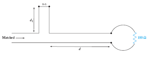
Chapter 10, Problem 10.36P
The two-wire lines shown in Figure 10.36 are all lossless and have
Expert Solution & Answer
Want to see the full answer?
Check out a sample textbook solution
Students have asked these similar questions
6-A lossless T.L. has Zo = 100 N and is loaded by an unknown impedance
Its VSWR is 4 and the first voltage maximum is A/8 from the load .
Find the load impedance .
10 V
In the lossless transmission line system shown, the switch S is closed at t = 0.
a. Find the reflection coefficient IJ.
b. Find the reflection coefficient TL.
c. Find the transmission coefficient t+.
d. Complete the following reflection diagram in order to determine the total
voltages VA, VB, Vc, and VD.
752
201=7522
T
VA= 5
em
|V₁ = ?
|V₂ = ?
Figure P6
70₂= Son
T
V₂=?
4
[V=0]
Vc
15022
Normalized admittance values zL= 0.4 - j0.3 with two load impedances connected in parallel with a 50 cm long coaxial line insulated with dielectric (€1 = 3) It is connected to a source with an operating frequency of 1 GHz. Find the distance of the voltage max and min to the load and the normalized input impedance of the line.
Chapter 10 Solutions
Engineering Electromagnetics
Ch. 10 - The parameters of a certain transmission line...Ch. 10 - A sinusoidal wave on a transmission line is...Ch. 10 - Prob. 10.3PCh. 10 - A sinusoidal voltage V0, frequency , and phase...Ch. 10 - Two voltage waves of equal amplitude V0 and radian...Ch. 10 - A 50 load is attached to a 50-m section of the...Ch. 10 - Prob. 10.7PCh. 10 - An absolute measure of power is the dBm scale, in...Ch. 10 - A 100-m transmission line is used to propagate a...Ch. 10 - Two lossless transmission lines having different...
Ch. 10 - Two voltage waves of equal amplitude V0, which...Ch. 10 - In a circuit in which a sinusoidal voltage source...Ch. 10 - The skin effect mechanism in transmission lines is...Ch. 10 - A lossless transmission line having characteristic...Ch. 10 - Figure 10.29 See Problem 10.15. For the...Ch. 10 - A 100 lossless transmission line is connected to a...Ch. 10 - Determine the average power absorbed by each...Ch. 10 - The line shown in Figure 10.31 is lossless. Find s...Ch. 10 - A lossless transmission line is 50 cm in length...Ch. 10 - (a) Determine s on the transmission line of Figure...Ch. 10 - Prob. 10.21PCh. 10 - Prob. 10.22PCh. 10 - The normalized load on a lossless transmission...Ch. 10 - Prob. 10.24PCh. 10 - Prob. 10.25PCh. 10 - A 75 lossless line is of length 1.2 . It is...Ch. 10 - Prob. 10.27PCh. 10 - The wavelength on a certain lossless line is 10...Ch. 10 - Prob. 10.29PCh. 10 - A two-wire line constructed of lossless wire of...Ch. 10 - In order to compare the relative sharpness of the...Ch. 10 - In Figure 10.17, let ZL=250 and Z0=50. Find the...Ch. 10 - In Figure 10.17, let ZL=100+j150 and Z0=100. Find...Ch. 10 - The lossless line shown in Figure 10.35 is...Ch. 10 - Prob. 10.35PCh. 10 - The two-wire lines shown in Figure 10.36 are all...Ch. 10 - Prob. 10.37PCh. 10 - Repeat Problem 10.37, with, Z0=50 and RL=Rg=25....Ch. 10 - In the transmission line of Figure 10.20, Z0=50,...Ch. 10 - In the charged line of Figure 10.25, the...Ch. 10 - In the transmission line of Figure 10.37, the...Ch. 10 - Figure 10.38 See Problem 10.42. A simple frozen...Ch. 10 - Figure 10.39 See Problem 10.43. In Figure 10.39,...
Knowledge Booster


Learn more about
Need a deep-dive on the concept behind this application? Look no further. Learn more about this topic, electrical-engineering and related others by exploring similar questions and additional content below.Similar questions
- 1. a. A purely reactive load impedance Z₁ =jX terminates a transmission line. Prove that the reflection coefficient magnitude |K| is always unity, assuming the characteristic impedance Zo is real. What is the VSWR of the line in this case? b. Consider the transmission line in the figure. i. Determine the SWR on transmission line ii. The input impedance If=102, find I, in the figure. WC 100/0*V] 20 922 Air, lossless Z-50 £2 2.72 40 2 ele 3002arrow_forwardb) A battery with an emf of 18V and series resistance Zg-2Z, are connected at t = 0 to the sending end of a lossless T.L which is a short-circuited at the far end. The characteristic impedance for this uniform T.L is Zo-500. Sketch the voltage as a function of time for both ends. (Use Zig-Zag diagram).arrow_forwardb. Determine what is the necessary length and characteristic impedance of a cable to be used as a quarter-wave matching transformer so that it can eliminate the standing waves and subsequently provide a matched condition for a 180 O resistive load fed from a 45 0 transmission line. This condition is to exist for a frequency of 95 MHz. Given a velocity factor = 1.0.arrow_forward
- A system has a forward power of 60 W, reflected power of 3 W, and transmission line loss of –3 dB. What will be the observed loss on the ground? A system has a forward power of 200 W and a reflected power of 15 W, what is the return loss?arrow_forwardA 702 high-frequency lossless line is used at a frequency where 2 = 80cm with a load of 140+j91 2 a. Calculate the reflection coefficient and the SWR b. Determine the distance to the first voltage minimum from the load c. Determine the distance to the first voltage maximum from the load d. Calculate the impedance at the point where maximum voltages occurarrow_forwarda line characteristic impedance 600 ohm and 3 db loss is a half wavelength .it is fed by a source of emf 5v and impedance 1 kilo ohm and is terminated by aload 0f 400 ohms impedance .calculate the load voltage ..arrow_forward
- b) A 6052 characteristic impedance transmission line is fed by a DC source of 100V with an internal resistance of 4002. The line is 200m long and has a dielectric constant of 2.25. The load impedance is 12002. Calculate: i. The load reflection coefficient. ii. The source reflection coefficient. iii. What is the voltage at the source terminals just before AND just after 2us?arrow_forwardQ) A source of 10 V and frequency 1000 KHz with internal resistance of 10 2 is connected to the sending end of a transmission line which can be represented by a resistance of 70 Q in series with capacitance of 0.001 uF connected across the line at the receiving end. An inductive load of inductance 0.002 H and resistance 100 is connected across the receiving end of the line. Determine the load current.arrow_forward!EMERGENCY! Normalized admittance values zI= 0.4 - j0.3 with two load impedances connected in parallel with a 50 cm long coaxial line insulated with dielectric (€1 = 3) It is connected to a source with an operating frequency of 1 GHz. Find the distance of the voltage max and min to the load and the normalized input impedance of the line.arrow_forward
- In the transmission line below, Z0=50 ohm operating frequency is 100MHz and wave speed is given as v=10^8 m/s. If d=46cm and l=14cm are chosen to avoid any back reflection in the transmission line, the load impedance ZL=?arrow_forwardWhat is the value of the input impedance half wavelength from the load? a. ZL b. minimum c. maximum d. Zo For an open circuit line, the location of the first maximum current is ____. a. at the load b. λ/4 from the load c. 0.125λ from the load d. λ/2 from the load What is the phase difference between two points that are half wavelength apart? a. 90° b. 45° c. 180° d. 270°arrow_forwardA 105MHz, 90 v peak signal is incident on a 50-ohm transmission line. The line is 125m long and is terminated in 300-ohm load. What is the SWR for this situation? Find the reflection coefficient.arrow_forward
arrow_back_ios
SEE MORE QUESTIONS
arrow_forward_ios
Recommended textbooks for you
 Introductory Circuit Analysis (13th Edition)Electrical EngineeringISBN:9780133923605Author:Robert L. BoylestadPublisher:PEARSON
 Delmar's Standard Textbook Of ElectricityElectrical EngineeringISBN:9781337900348Author:Stephen L. HermanPublisher:Cengage Learning
 Programmable Logic ControllersElectrical EngineeringISBN:9780073373843Author:Frank D. PetruzellaPublisher:McGraw-Hill Education
 Fundamentals of Electric CircuitsElectrical EngineeringISBN:9780078028229Author:Charles K Alexander, Matthew SadikuPublisher:McGraw-Hill Education
 Electric Circuits. (11th Edition)Electrical EngineeringISBN:9780134746968Author:James W. Nilsson, Susan RiedelPublisher:PEARSON
 Engineering ElectromagneticsElectrical EngineeringISBN:9780078028151Author:Hayt, William H. (william Hart), Jr, BUCK, John A.Publisher:Mcgraw-hill Education,
Introductory Circuit Analysis (13th Edition)
Electrical Engineering
ISBN:9780133923605
Author:Robert L. Boylestad
Publisher:PEARSON
Delmar's Standard Textbook Of Electricity
Electrical Engineering
ISBN:9781337900348
Author:Stephen L. Herman
Publisher:Cengage Learning
Programmable Logic Controllers
Electrical Engineering
ISBN:9780073373843
Author:Frank D. Petruzella
Publisher:McGraw-Hill Education
Fundamentals of Electric Circuits
Electrical Engineering
ISBN:9780078028229
Author:Charles K Alexander, Matthew Sadiku
Publisher:McGraw-Hill Education
Electric Circuits. (11th Edition)
Electrical Engineering
ISBN:9780134746968
Author:James W. Nilsson, Susan Riedel
Publisher:PEARSON
Engineering Electromagnetics
Electrical Engineering
ISBN:9780078028151
Author:Hayt, William H. (william Hart), Jr, BUCK, John A.
Publisher:Mcgraw-hill Education,
How do Electric Transmission Lines Work?; Author: Practical Engineering;https://www.youtube.com/watch?v=qjY31x0m3d8;License: Standard Youtube License