
Engineering Electromagnetics
9th Edition
ISBN: 9780078028151
Author: Hayt, William H. (william Hart), Jr, BUCK, John A.
Publisher: Mcgraw-hill Education,
expand_more
expand_more
format_list_bulleted
Concept explainers
Videos
Textbook Question
Chapter 10, Problem 10.30P
A two-wire line constructed of lossless wire of circular cross section is gradually flared into a coupling loop that looks like an eggbeater. At the point X, indicated by the arrow in Figure 10.34, a short circuit is placed across the line. A probe is moved along the line and indicates that the first voltage minimum to the left of X is 16 cm from X. With the short circuit removed, a voltage minimum is found 5 cm to the left of X, and a voltage maximum is located that is 3 times the voltage of the minimum. Use the Smith chart to determine (a) f; (b) s; (c) the normalized input impedance of the eggbeater as seen looking to the right at point X.
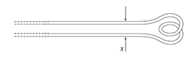
Figure 10.34 See Problem 10.30.
Expert Solution & Answer
Want to see the full answer?
Check out a sample textbook solution
Students have asked these similar questions
Explain why the maximum value of the duty cycle must be limited in certain boost choppers.
//(L-7)
The value of critical clearing angle can be directly determined by using step by step method.Select one:True
fals
400Ω
A
k=0.9
600Ω
B
k=0.8
66Ω
600Ω
Chapter 10 Solutions
Engineering Electromagnetics
Ch. 10 - The parameters of a certain transmission line...Ch. 10 - A sinusoidal wave on a transmission line is...Ch. 10 - Prob. 10.3PCh. 10 - A sinusoidal voltage V0, frequency , and phase...Ch. 10 - Two voltage waves of equal amplitude V0 and radian...Ch. 10 - A 50 load is attached to a 50-m section of the...Ch. 10 - Prob. 10.7PCh. 10 - An absolute measure of power is the dBm scale, in...Ch. 10 - A 100-m transmission line is used to propagate a...Ch. 10 - Two lossless transmission lines having different...
Ch. 10 - Two voltage waves of equal amplitude V0, which...Ch. 10 - In a circuit in which a sinusoidal voltage source...Ch. 10 - The skin effect mechanism in transmission lines is...Ch. 10 - A lossless transmission line having characteristic...Ch. 10 - Figure 10.29 See Problem 10.15. For the...Ch. 10 - A 100 lossless transmission line is connected to a...Ch. 10 - Determine the average power absorbed by each...Ch. 10 - The line shown in Figure 10.31 is lossless. Find s...Ch. 10 - A lossless transmission line is 50 cm in length...Ch. 10 - (a) Determine s on the transmission line of Figure...Ch. 10 - Prob. 10.21PCh. 10 - Prob. 10.22PCh. 10 - The normalized load on a lossless transmission...Ch. 10 - Prob. 10.24PCh. 10 - Prob. 10.25PCh. 10 - A 75 lossless line is of length 1.2 . It is...Ch. 10 - Prob. 10.27PCh. 10 - The wavelength on a certain lossless line is 10...Ch. 10 - Prob. 10.29PCh. 10 - A two-wire line constructed of lossless wire of...Ch. 10 - In order to compare the relative sharpness of the...Ch. 10 - In Figure 10.17, let ZL=250 and Z0=50. Find the...Ch. 10 - In Figure 10.17, let ZL=100+j150 and Z0=100. Find...Ch. 10 - The lossless line shown in Figure 10.35 is...Ch. 10 - Prob. 10.35PCh. 10 - The two-wire lines shown in Figure 10.36 are all...Ch. 10 - Prob. 10.37PCh. 10 - Repeat Problem 10.37, with, Z0=50 and RL=Rg=25....Ch. 10 - In the transmission line of Figure 10.20, Z0=50,...Ch. 10 - In the charged line of Figure 10.25, the...Ch. 10 - In the transmission line of Figure 10.37, the...Ch. 10 - Figure 10.38 See Problem 10.42. A simple frozen...Ch. 10 - Figure 10.39 See Problem 10.43. In Figure 10.39,...
Knowledge Booster


Learn more about
Need a deep-dive on the concept behind this application? Look no further. Learn more about this topic, electrical-engineering and related others by exploring similar questions and additional content below.Similar questions
- In the Transmission Line Simulator, the Transmission Line is composed of which parameter/s? O A. The Shunt Conductance Only O B. The Series Impedance and Shunt Capacitance O C. The Shunt Capacitance Only O D. The Series Impedance Onlyarrow_forwardIn a series eaperiment with R, =1n and R, 4n across a power Supply E, the slope g (E, v, ) and of CE,V2) are re spechively (...) C ---- ) (a) 2 , 3 ( b) 5 , 1.25 (e) 2.15 , 5 (d) 3, 2arrow_forwardWhat is load curvearrow_forward
- how was the load 300<-36.86 achieved?arrow_forwardCan we used information signal has frequency 500 Hz? why? at AM-SSBarrow_forwardWhy is the conduction angle greater with an inductive load than with a purely resistive load? Also, what point in a single-phase ac waveform is used as a reference point for timing the thyristor gate pulses?arrow_forward
- In an AC LVDT system, measuring the output voltage alone gives anindication of the displacement from the center, but not the direction ofdisplacement. Explain why, and also explain a method for solving thisproblem.arrow_forwardThe VSWR on an 50-Ohm transmission line is 5. The distance between successive voltageminima is 80 cm while the distance from the load to the first minimum is 30 cm. What are thereflection coefficient and load impedancearrow_forwardWhat is the effect of value of filter capacitor on ripple voltage?arrow_forward
- Can I have help with problem 9.9?arrow_forward2. When a large shunt capacitor is suddenly connected in parallel with the load bus in the distribution feeder, what would happen to this bus current? O A. Increase B. Decrease D. None of Abovearrow_forwardIdeally, a dc load line is a straight line drawn on collector characteristic curves between which of the following? Please select one: a. Q Point and shear b. Q Point and saturation c. V_CE (interrupt) and I_C (sat) d. I_b = 0 and I_B = I_C/ß_DCarrow_forward
arrow_back_ios
SEE MORE QUESTIONS
arrow_forward_ios
Recommended textbooks for you
 Introductory Circuit Analysis (13th Edition)Electrical EngineeringISBN:9780133923605Author:Robert L. BoylestadPublisher:PEARSON
 Delmar's Standard Textbook Of ElectricityElectrical EngineeringISBN:9781337900348Author:Stephen L. HermanPublisher:Cengage Learning
 Programmable Logic ControllersElectrical EngineeringISBN:9780073373843Author:Frank D. PetruzellaPublisher:McGraw-Hill Education
 Fundamentals of Electric CircuitsElectrical EngineeringISBN:9780078028229Author:Charles K Alexander, Matthew SadikuPublisher:McGraw-Hill Education
 Electric Circuits. (11th Edition)Electrical EngineeringISBN:9780134746968Author:James W. Nilsson, Susan RiedelPublisher:PEARSON
 Engineering ElectromagneticsElectrical EngineeringISBN:9780078028151Author:Hayt, William H. (william Hart), Jr, BUCK, John A.Publisher:Mcgraw-hill Education,
Introductory Circuit Analysis (13th Edition)
Electrical Engineering
ISBN:9780133923605
Author:Robert L. Boylestad
Publisher:PEARSON
Delmar's Standard Textbook Of Electricity
Electrical Engineering
ISBN:9781337900348
Author:Stephen L. Herman
Publisher:Cengage Learning
Programmable Logic Controllers
Electrical Engineering
ISBN:9780073373843
Author:Frank D. Petruzella
Publisher:McGraw-Hill Education
Fundamentals of Electric Circuits
Electrical Engineering
ISBN:9780078028229
Author:Charles K Alexander, Matthew Sadiku
Publisher:McGraw-Hill Education
Electric Circuits. (11th Edition)
Electrical Engineering
ISBN:9780134746968
Author:James W. Nilsson, Susan Riedel
Publisher:PEARSON
Engineering Electromagnetics
Electrical Engineering
ISBN:9780078028151
Author:Hayt, William H. (william Hart), Jr, BUCK, John A.
Publisher:Mcgraw-hill Education,
How do Electric Transmission Lines Work?; Author: Practical Engineering;https://www.youtube.com/watch?v=qjY31x0m3d8;License: Standard Youtube License