
Engineering Electromagnetics
9th Edition
ISBN: 9780078028151
Author: Hayt, William H. (william Hart), Jr, BUCK, John A.
Publisher: Mcgraw-hill Education,
expand_more
expand_more
format_list_bulleted
Concept explainers
Videos
Textbook Question
Chapter 10, Problem 10.18P
The line shown in Figure 10.31 is lossless. Find s on both sections 1 and 2.
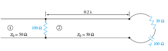
Figure 10.31 See Problem 10.8
Expert Solution & Answer
Want to see the full answer?
Check out a sample textbook solution
Students have asked these similar questions
Electrical Engineering
A lossless transmission line has a capacitance per unit length of 90 uF/m (microFarad/meter) and an inductance per unit length of 1 nH/m. The load impedance ZI is purely resistive. Both the load impedance and the generator impedance are 50 ohms. Source voltage amplitude is unknown at this point. Find the characteristic impedance and the propagation velocity for this transmission line!
5-A lossless T.L. has Zo = 100 Q and is loaded by ZL. The VSWR = 2. The first two
voltage minima are located at z= -10 and -35 Cm from the load where z = 0.
Determine ZL.
10. The capacitance per unit length and the characteristic impedance of a
lossless transmission line are C and Z0 respectively. The velocity of a
travelling wave on the transmission line is
(a) ZoC
(b) 1/(ZoC)
(c) Zo/C
(d) C/Zo
Chapter 10 Solutions
Engineering Electromagnetics
Ch. 10 - The parameters of a certain transmission line...Ch. 10 - A sinusoidal wave on a transmission line is...Ch. 10 - Prob. 10.3PCh. 10 - A sinusoidal voltage V0, frequency , and phase...Ch. 10 - Two voltage waves of equal amplitude V0 and radian...Ch. 10 - A 50 load is attached to a 50-m section of the...Ch. 10 - Prob. 10.7PCh. 10 - An absolute measure of power is the dBm scale, in...Ch. 10 - A 100-m transmission line is used to propagate a...Ch. 10 - Two lossless transmission lines having different...
Ch. 10 - Two voltage waves of equal amplitude V0, which...Ch. 10 - In a circuit in which a sinusoidal voltage source...Ch. 10 - The skin effect mechanism in transmission lines is...Ch. 10 - A lossless transmission line having characteristic...Ch. 10 - Figure 10.29 See Problem 10.15. For the...Ch. 10 - A 100 lossless transmission line is connected to a...Ch. 10 - Determine the average power absorbed by each...Ch. 10 - The line shown in Figure 10.31 is lossless. Find s...Ch. 10 - A lossless transmission line is 50 cm in length...Ch. 10 - (a) Determine s on the transmission line of Figure...Ch. 10 - Prob. 10.21PCh. 10 - Prob. 10.22PCh. 10 - The normalized load on a lossless transmission...Ch. 10 - Prob. 10.24PCh. 10 - Prob. 10.25PCh. 10 - A 75 lossless line is of length 1.2 . It is...Ch. 10 - Prob. 10.27PCh. 10 - The wavelength on a certain lossless line is 10...Ch. 10 - Prob. 10.29PCh. 10 - A two-wire line constructed of lossless wire of...Ch. 10 - In order to compare the relative sharpness of the...Ch. 10 - In Figure 10.17, let ZL=250 and Z0=50. Find the...Ch. 10 - In Figure 10.17, let ZL=100+j150 and Z0=100. Find...Ch. 10 - The lossless line shown in Figure 10.35 is...Ch. 10 - Prob. 10.35PCh. 10 - The two-wire lines shown in Figure 10.36 are all...Ch. 10 - Prob. 10.37PCh. 10 - Repeat Problem 10.37, with, Z0=50 and RL=Rg=25....Ch. 10 - In the transmission line of Figure 10.20, Z0=50,...Ch. 10 - In the charged line of Figure 10.25, the...Ch. 10 - In the transmission line of Figure 10.37, the...Ch. 10 - Figure 10.38 See Problem 10.42. A simple frozen...Ch. 10 - Figure 10.39 See Problem 10.43. In Figure 10.39,...
Knowledge Booster


Learn more about
Need a deep-dive on the concept behind this application? Look no further. Learn more about this topic, electrical-engineering and related others by exploring similar questions and additional content below.Similar questions
- C- Considering the model of a medium length transmission line where the capacitive effect is equally divided at the beginning and the end of the transmission line, draw the phasor diagram for a lagging power factor load condition. You have to begin with VR, IR and end with VS, IS. THE ENDarrow_forward!EMERGENCY! Normalized admittance values zI= 0.4 - j0.3 with two load impedances connected in parallel with a 50 cm long coaxial line insulated with dielectric (€1 = 3) It is connected to a source with an operating frequency of 1 GHz. Find the distance of the voltage max and min to the load and the normalized input impedance of the line.arrow_forward"In medium transmission line modeling, which of the parameter is considered to be lumped?" Resistance Inductance Capacitance All options are correctarrow_forward
- For the given power transfer, a star system is associated with larger line currents and a delta system is associated with a larger line voltage. Select one: O True O False Jump to...arrow_forward4. (a) A transmission line with a characteristic impedance of 100 has a load of 1 k2 resistance in parallel with a 0.005 µF capacitor connected across the far end. A surge voltage of magnitude 10 kV and unit function form (i.e. step function) travels along the line. Derive an expression for the time variation of the voltage across the load, and calculate the value of this voltage 10us after the arrival of the wave front of the surgearrow_forwardA. Find the following requirements in plotting the root locus. • number of branches • number of asymptotes • asymptote real-axis intercept • asymptote line angles • real-axis break-away points / break-in points • points at the jw-crossing B. Manually plot the root locus based on the requirements from item A.arrow_forward
- PLORA transmisson Line is lossless and is 30 m Long it's terminated in load impedance of Zi-(30+J20)52 at Prequency of to mHz the inductonce capacitance of the line are l Let0onH/m c=20pt/m. Find the input impedane ol the source end and the midpoint of the Line ?arrow_forwardThe effect of the Shunt Capacitance is negligible only if the length of the Transmission Line does not exceed how many kilometers? A. 240 kms B. 120 km C. 300 km D. 80 kmsarrow_forwardg) Why the Capacitance effect is neglected in Short Transmission Line. h) Distinguish between Lumped or Distributed elements in a Transmission Line.arrow_forward
- Normalized admittance values zL= 0.4 - j0.3 with two load impedances connected in parallel with a 50 cm long coaxial line insulated with dielectric (€1 = 3) It is connected to a source with an operating frequency of 1 GHz. Find the distance of the voltage max and min to the load and the normalized input impedance of the line.arrow_forwardA 105MHz, 90 v peak signal is incident on a 50-ohm transmission line. The line is 125m long and is terminated in 300-ohm load. What is the SWR for this situation? Find the reflection coefficient.arrow_forward10. A single phase double circuit transmission line is shown in figure. Conductor 1 and 2 in parallel form one path while conductor 1' and 2' in parallel form the return path. The current is equally shared by the two parallel lines. Determine the total inductance per km of the line. The diameter of each conductor is 2.0cm. 1.0 m 3.0 m- ||arrow_forward
arrow_back_ios
SEE MORE QUESTIONS
arrow_forward_ios
Recommended textbooks for you
 Introductory Circuit Analysis (13th Edition)Electrical EngineeringISBN:9780133923605Author:Robert L. BoylestadPublisher:PEARSON
 Delmar's Standard Textbook Of ElectricityElectrical EngineeringISBN:9781337900348Author:Stephen L. HermanPublisher:Cengage Learning
 Programmable Logic ControllersElectrical EngineeringISBN:9780073373843Author:Frank D. PetruzellaPublisher:McGraw-Hill Education
 Fundamentals of Electric CircuitsElectrical EngineeringISBN:9780078028229Author:Charles K Alexander, Matthew SadikuPublisher:McGraw-Hill Education
 Electric Circuits. (11th Edition)Electrical EngineeringISBN:9780134746968Author:James W. Nilsson, Susan RiedelPublisher:PEARSON
 Engineering ElectromagneticsElectrical EngineeringISBN:9780078028151Author:Hayt, William H. (william Hart), Jr, BUCK, John A.Publisher:Mcgraw-hill Education,
Introductory Circuit Analysis (13th Edition)
Electrical Engineering
ISBN:9780133923605
Author:Robert L. Boylestad
Publisher:PEARSON
Delmar's Standard Textbook Of Electricity
Electrical Engineering
ISBN:9781337900348
Author:Stephen L. Herman
Publisher:Cengage Learning
Programmable Logic Controllers
Electrical Engineering
ISBN:9780073373843
Author:Frank D. Petruzella
Publisher:McGraw-Hill Education
Fundamentals of Electric Circuits
Electrical Engineering
ISBN:9780078028229
Author:Charles K Alexander, Matthew Sadiku
Publisher:McGraw-Hill Education
Electric Circuits. (11th Edition)
Electrical Engineering
ISBN:9780134746968
Author:James W. Nilsson, Susan Riedel
Publisher:PEARSON
Engineering Electromagnetics
Electrical Engineering
ISBN:9780078028151
Author:Hayt, William H. (william Hart), Jr, BUCK, John A.
Publisher:Mcgraw-hill Education,
How do Electric Transmission Lines Work?; Author: Practical Engineering;https://www.youtube.com/watch?v=qjY31x0m3d8;License: Standard Youtube License