
Engineering Electromagnetics
9th Edition
ISBN: 9780078028151
Author: Hayt, William H. (william Hart), Jr, BUCK, John A.
Publisher: Mcgraw-hill Education,
expand_more
expand_more
format_list_bulleted
Concept explainers
Videos
Textbook Question
Chapter 10, Problem 10.41P
In the transmission line of Figure 10.37, the switch is located midway down the line and is closed t = 0. Construct a voltage reflection diagram for this case, where RL = Z0. Plot the load resistor voltage as a function of time.
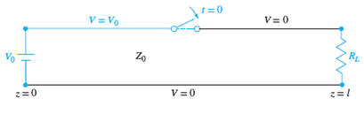
Figure 10.7 See Problem 10.41.
Expert Solution & Answer
Want to see the full answer?
Check out a sample textbook solution
Students have asked these similar questions
Problem 10. For the double-beam oscilloscope dis-
plays shown in Figure 10.20 determine (a) their
frequency, (b) their r.m.s. values, (c) their phase dif-
ference. The 'time/cm' switch is on 100 μs/cm and the
'volts/cm' switch on 2 V/cm.
B
N
A
Figure 10.20
• Create an instance of Qm/prmp/Cmax with at least 3 jobs and 2
machines (at different speeds).
Apply LRPT-FM rule and show the resulting schedule on a Gannt
chart.
how was the load 300<-36.86 achieved?
Chapter 10 Solutions
Engineering Electromagnetics
Ch. 10 - The parameters of a certain transmission line...Ch. 10 - A sinusoidal wave on a transmission line is...Ch. 10 - Prob. 10.3PCh. 10 - A sinusoidal voltage V0, frequency , and phase...Ch. 10 - Two voltage waves of equal amplitude V0 and radian...Ch. 10 - A 50 load is attached to a 50-m section of the...Ch. 10 - Prob. 10.7PCh. 10 - An absolute measure of power is the dBm scale, in...Ch. 10 - A 100-m transmission line is used to propagate a...Ch. 10 - Two lossless transmission lines having different...
Ch. 10 - Two voltage waves of equal amplitude V0, which...Ch. 10 - In a circuit in which a sinusoidal voltage source...Ch. 10 - The skin effect mechanism in transmission lines is...Ch. 10 - A lossless transmission line having characteristic...Ch. 10 - Figure 10.29 See Problem 10.15. For the...Ch. 10 - A 100 lossless transmission line is connected to a...Ch. 10 - Determine the average power absorbed by each...Ch. 10 - The line shown in Figure 10.31 is lossless. Find s...Ch. 10 - A lossless transmission line is 50 cm in length...Ch. 10 - (a) Determine s on the transmission line of Figure...Ch. 10 - Prob. 10.21PCh. 10 - Prob. 10.22PCh. 10 - The normalized load on a lossless transmission...Ch. 10 - Prob. 10.24PCh. 10 - Prob. 10.25PCh. 10 - A 75 lossless line is of length 1.2 . It is...Ch. 10 - Prob. 10.27PCh. 10 - The wavelength on a certain lossless line is 10...Ch. 10 - Prob. 10.29PCh. 10 - A two-wire line constructed of lossless wire of...Ch. 10 - In order to compare the relative sharpness of the...Ch. 10 - In Figure 10.17, let ZL=250 and Z0=50. Find the...Ch. 10 - In Figure 10.17, let ZL=100+j150 and Z0=100. Find...Ch. 10 - The lossless line shown in Figure 10.35 is...Ch. 10 - Prob. 10.35PCh. 10 - The two-wire lines shown in Figure 10.36 are all...Ch. 10 - Prob. 10.37PCh. 10 - Repeat Problem 10.37, with, Z0=50 and RL=Rg=25....Ch. 10 - In the transmission line of Figure 10.20, Z0=50,...Ch. 10 - In the charged line of Figure 10.25, the...Ch. 10 - In the transmission line of Figure 10.37, the...Ch. 10 - Figure 10.38 See Problem 10.42. A simple frozen...Ch. 10 - Figure 10.39 See Problem 10.43. In Figure 10.39,...
Knowledge Booster


Learn more about
Need a deep-dive on the concept behind this application? Look no further. Learn more about this topic, electrical-engineering and related others by exploring similar questions and additional content below.Similar questions
- 30) In a lightly loaded long distance EHV lines, line loading is and has a power factor: (A) Capacitive, lagging. (B) Capacitive, leading (C) Inductive, lagging (D) Inductive, leading. please contact me in whatsapp +962782974574arrow_forwardExplain what miller theorem is confused? What is millers capacitance?arrow_forwardIn a series eaperiment with R, =1n and R, 4n across a power Supply E, the slope g (E, v, ) and of CE,V2) are re spechively (...) C ---- ) (a) 2 , 3 ( b) 5 , 1.25 (e) 2.15 , 5 (d) 3, 2arrow_forward
- The period of this signal is about------ ms (milliseconds). The oscilloscope range selector determines the scale on the screen. That means number of volts per line for amplitude vertical (v/div) and the number of milliseconds per line for time horizontally (ms/div).arrow_forward9.28. Consider an LTI system for which the system function H(s) has the pole-zero pattern shown in Figure P9.28. -X-X- -2 -1 Im -X- O +1 +2 Re Figure P9.28 (a) Indicate all possible ROCs that can be associated with this pole-zero pattern. (b) For each ROC identified in part (a), specify whether the associated system is stable and/or causal.arrow_forwarda) Determine ?? ??⃗ and ?? ??⃗ using CDR. b) Sketch the phasor diagram for the currents.arrow_forward
- Discuss the impact of cable impedance on signal quality in high-speed data transmission. How does impedance matching play a role in cable design?arrow_forward5/The Voltage Regulation of a Transmission Line (in the simulator) depends on which parameter/s? A. Both the Transmission Line Resistance and Inductance B. The Transmission Line Shunt Capacitance only C. The Transmission Line Inductance only D. The Transmission Line Resistance onlyarrow_forwardExample.2: A sinusoidal wave m(t) = 15csin2500nt, is applied to an FM generator that has a frequency modulation constant of 50 Hz/volt. Determine the frequency deviation and modulating index.arrow_forward
- 1. Discuss the influence of the bypass, coupling, internal, and stray capacitances on the frequency response.arrow_forwardThe period of this signal is about ____ ms (milliseconds). Use this picture for 2 additional questions below. The oscilloscope range selector determines the scale on the screen. That means number of Volts per line for amplitude vertical (V/div) and the number of milliseconds per line for time horizontally (ms/div). The frequency of the signal in previous question is about ____ Hz. The peak to peak amplitude of the signal on the oscilloscope on first question is about ___ Volt(s). During sound digitizing the sound frequencies ranged from 200 Hz to 2.2 kHz. Based on Nyquist theorem the sampling frequency should be at least ____ Hz. Select the FM Radio Quality recording format on the picture below and calculate the size of a 30 seconds uncompressed audio file (like a WAV file) in kB (kilo Bytes). This is a ____ mega pixels picture. Based on the same image file properties screen shown in previous question, the size of…arrow_forwardConsider a 10W power transmitter and a 30dB transmission antenna, the EIRP value will be: Select one or more than one: a. The value of the EIRP is: 10000watt b. The EIRP value is :50dBW c. The EIRP value is: 200 Watt d. The EIRP value is: 40dBwarrow_forward
arrow_back_ios
SEE MORE QUESTIONS
arrow_forward_ios
Recommended textbooks for you
 Introductory Circuit Analysis (13th Edition)Electrical EngineeringISBN:9780133923605Author:Robert L. BoylestadPublisher:PEARSON
 Delmar's Standard Textbook Of ElectricityElectrical EngineeringISBN:9781337900348Author:Stephen L. HermanPublisher:Cengage Learning
 Programmable Logic ControllersElectrical EngineeringISBN:9780073373843Author:Frank D. PetruzellaPublisher:McGraw-Hill Education
 Fundamentals of Electric CircuitsElectrical EngineeringISBN:9780078028229Author:Charles K Alexander, Matthew SadikuPublisher:McGraw-Hill Education
 Electric Circuits. (11th Edition)Electrical EngineeringISBN:9780134746968Author:James W. Nilsson, Susan RiedelPublisher:PEARSON
 Engineering ElectromagneticsElectrical EngineeringISBN:9780078028151Author:Hayt, William H. (william Hart), Jr, BUCK, John A.Publisher:Mcgraw-hill Education,
Introductory Circuit Analysis (13th Edition)
Electrical Engineering
ISBN:9780133923605
Author:Robert L. Boylestad
Publisher:PEARSON
Delmar's Standard Textbook Of Electricity
Electrical Engineering
ISBN:9781337900348
Author:Stephen L. Herman
Publisher:Cengage Learning
Programmable Logic Controllers
Electrical Engineering
ISBN:9780073373843
Author:Frank D. Petruzella
Publisher:McGraw-Hill Education
Fundamentals of Electric Circuits
Electrical Engineering
ISBN:9780078028229
Author:Charles K Alexander, Matthew Sadiku
Publisher:McGraw-Hill Education
Electric Circuits. (11th Edition)
Electrical Engineering
ISBN:9780134746968
Author:James W. Nilsson, Susan Riedel
Publisher:PEARSON
Engineering Electromagnetics
Electrical Engineering
ISBN:9780078028151
Author:Hayt, William H. (william Hart), Jr, BUCK, John A.
Publisher:Mcgraw-hill Education,
How does an Antenna work? | ICT #4; Author: Lesics;https://www.youtube.com/watch?v=ZaXm6wau-jc;License: Standard Youtube License