
Engineering Electromagnetics
9th Edition
ISBN: 9780078028151
Author: Hayt, William H. (william Hart), Jr, BUCK, John A.
Publisher: Mcgraw-hill Education,
expand_more
expand_more
format_list_bulleted
Concept explainers
Videos
Textbook Question
Chapter 10, Problem 10.42P
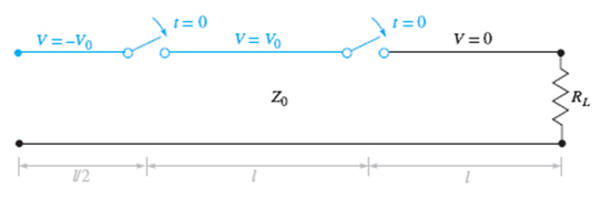
Figure 10.38 See Problem 10.42.
A simple frozen wave generator is shown in Figure 10.38. Both switches are closed simultaneously at t = 0. Construct an appropriate voltage reflection diagram for the case in which RL = Z0. Determine and plot the load resistor voltage as a function of time.
Expert Solution & Answer
Want to see the full answer?
Check out a sample textbook solution
Students have asked these similar questions
Can I have help with problem 9.1?
1. Why sub transient current magnitude is large compare to steady state current?
A chopper circuit drives an inductive load from 390 DC supply. Given the load resistance as 8 Q, the average load current as 23 A and operating frequency is 480 Hz. When the chopper is ON, 7 V is dropped. Calculate
(a) conduction period (in milliseconds)
(b) blocking period of the chopper (in milliseconds)
(c) duty cycle of the chopper
(d) draw the ON and OFF time period waveform
(ii) Draw the circuit diagram of the single phase bridge rectifier which is used in two quadrant operation (RL load) and explain its operation.
Chapter 10 Solutions
Engineering Electromagnetics
Ch. 10 - The parameters of a certain transmission line...Ch. 10 - A sinusoidal wave on a transmission line is...Ch. 10 - Prob. 10.3PCh. 10 - A sinusoidal voltage V0, frequency , and phase...Ch. 10 - Two voltage waves of equal amplitude V0 and radian...Ch. 10 - A 50 load is attached to a 50-m section of the...Ch. 10 - Prob. 10.7PCh. 10 - An absolute measure of power is the dBm scale, in...Ch. 10 - A 100-m transmission line is used to propagate a...Ch. 10 - Two lossless transmission lines having different...
Ch. 10 - Two voltage waves of equal amplitude V0, which...Ch. 10 - In a circuit in which a sinusoidal voltage source...Ch. 10 - The skin effect mechanism in transmission lines is...Ch. 10 - A lossless transmission line having characteristic...Ch. 10 - Figure 10.29 See Problem 10.15. For the...Ch. 10 - A 100 lossless transmission line is connected to a...Ch. 10 - Determine the average power absorbed by each...Ch. 10 - The line shown in Figure 10.31 is lossless. Find s...Ch. 10 - A lossless transmission line is 50 cm in length...Ch. 10 - (a) Determine s on the transmission line of Figure...Ch. 10 - Prob. 10.21PCh. 10 - Prob. 10.22PCh. 10 - The normalized load on a lossless transmission...Ch. 10 - Prob. 10.24PCh. 10 - Prob. 10.25PCh. 10 - A 75 lossless line is of length 1.2 . It is...Ch. 10 - Prob. 10.27PCh. 10 - The wavelength on a certain lossless line is 10...Ch. 10 - Prob. 10.29PCh. 10 - A two-wire line constructed of lossless wire of...Ch. 10 - In order to compare the relative sharpness of the...Ch. 10 - In Figure 10.17, let ZL=250 and Z0=50. Find the...Ch. 10 - In Figure 10.17, let ZL=100+j150 and Z0=100. Find...Ch. 10 - The lossless line shown in Figure 10.35 is...Ch. 10 - Prob. 10.35PCh. 10 - The two-wire lines shown in Figure 10.36 are all...Ch. 10 - Prob. 10.37PCh. 10 - Repeat Problem 10.37, with, Z0=50 and RL=Rg=25....Ch. 10 - In the transmission line of Figure 10.20, Z0=50,...Ch. 10 - In the charged line of Figure 10.25, the...Ch. 10 - In the transmission line of Figure 10.37, the...Ch. 10 - Figure 10.38 See Problem 10.42. A simple frozen...Ch. 10 - Figure 10.39 See Problem 10.43. In Figure 10.39,...
Knowledge Booster


Learn more about
Need a deep-dive on the concept behind this application? Look no further. Learn more about this topic, electrical-engineering and related others by exploring similar questions and additional content below.Similar questions
- Can someone help me try to understand the effect of Capacitance Multiplier Design Parameters on Power Supply Noise Reduction? Please also provide mathematical equation and make it computerized so I can unnderstand it better. PLEASE JUST REJECT IT IF YOU CAN'T HELP ME. THANKS!arrow_forwardWrite down the effect of ‘Load Tap Changer (LTC)’ on voltage stability and analyze it using P-U (nose) curve .arrow_forwardHow did 2 + j8ohms become 2 + 2 + j8ohms and then 8.9 ∠63.4? Like what did you do and why?arrow_forward
- (i) A chopper circuit drives an inductive load from 360 DC supply. Given the load resistance as 8 2, the average load current as 20 A and operating frequency is 480 Hz. When the chopper is ON, 7 V is dropped. Calculate (a) conduction period (in milliseconds) (b) blocking period of the chopper (in milliseconds) (c) duty cycle of the chopper (d) draw the ON and OFF time period waveform (ii) Draw the circuit diagram of the single phase bridge rectifier which is used in two quadrant operation (RL load) and explain its operation. · Duty Cycle ON period OFF periodarrow_forwardLow lagging power factor results in large voltage drop which results in poor.......... . (complete)arrow_forwardQ1) A single-phase AC voltage controller is connected to an inductive load with a resistance of 10 and load impedance angle of 45°. The input ac voltage is 230 V at 50 Hz. (a) Draw the load voltage waveforms and derive an expression for the rms load voltage. (b) Determine the maximum load voltage, maximum load current, and range of delay angie for which the load voltage does not change.arrow_forward
- Explain space harmonics and tooth harmonicsarrow_forward9.28. Consider an LTI system for which the system function H(s) has the pole-zero pattern shown in Figure P9.28. -X-X- -2 -1 Im -X- O +1 +2 Re Figure P9.28 (a) Indicate all possible ROCs that can be associated with this pole-zero pattern. (b) For each ROC identified in part (a), specify whether the associated system is stable and/or causal.arrow_forwardWhile Thevenizing a circuit between two . . terminals, VTH is equal to * rms voltage available in the circuit. O short circuit terminal voltage. O net voltage available in the circuit. O open circuit terminal voltage. )arrow_forward
- Figure-10.8 Example 10.4 A single phase fully controlled converter bridge is used for electrical braking of a seprately excited dc motor. The dc motor load is represented by an equivalent circuit as shown in the figure. 230 V, 50 Hz www 20 150 V Assume that the load inductance is sufficient to ensure continous and ripple free load current. The firing angle of the bridge for a load current of 10 A will be (a) 44° = (b) 51° (c) 129° (d) 136°arrow_forwardWhy is the conduction angle greater with an inductive load than with a purely resistive load? Also, what point in a single-phase ac waveform is used as a reference point for timing the thyristor gate pulses?arrow_forwardHow many different load groups are there in power plants? Explain by drawing on a power-time curve.arrow_forward
arrow_back_ios
SEE MORE QUESTIONS
arrow_forward_ios
Recommended textbooks for you
 Introductory Circuit Analysis (13th Edition)Electrical EngineeringISBN:9780133923605Author:Robert L. BoylestadPublisher:PEARSON
 Delmar's Standard Textbook Of ElectricityElectrical EngineeringISBN:9781337900348Author:Stephen L. HermanPublisher:Cengage Learning
 Programmable Logic ControllersElectrical EngineeringISBN:9780073373843Author:Frank D. PetruzellaPublisher:McGraw-Hill Education
 Fundamentals of Electric CircuitsElectrical EngineeringISBN:9780078028229Author:Charles K Alexander, Matthew SadikuPublisher:McGraw-Hill Education
 Electric Circuits. (11th Edition)Electrical EngineeringISBN:9780134746968Author:James W. Nilsson, Susan RiedelPublisher:PEARSON
 Engineering ElectromagneticsElectrical EngineeringISBN:9780078028151Author:Hayt, William H. (william Hart), Jr, BUCK, John A.Publisher:Mcgraw-hill Education,
Introductory Circuit Analysis (13th Edition)
Electrical Engineering
ISBN:9780133923605
Author:Robert L. Boylestad
Publisher:PEARSON
Delmar's Standard Textbook Of Electricity
Electrical Engineering
ISBN:9781337900348
Author:Stephen L. Herman
Publisher:Cengage Learning
Programmable Logic Controllers
Electrical Engineering
ISBN:9780073373843
Author:Frank D. Petruzella
Publisher:McGraw-Hill Education
Fundamentals of Electric Circuits
Electrical Engineering
ISBN:9780078028229
Author:Charles K Alexander, Matthew Sadiku
Publisher:McGraw-Hill Education
Electric Circuits. (11th Edition)
Electrical Engineering
ISBN:9780134746968
Author:James W. Nilsson, Susan Riedel
Publisher:PEARSON
Engineering Electromagnetics
Electrical Engineering
ISBN:9780078028151
Author:Hayt, William H. (william Hart), Jr, BUCK, John A.
Publisher:Mcgraw-hill Education,
How does an Antenna work? | ICT #4; Author: Lesics;https://www.youtube.com/watch?v=ZaXm6wau-jc;License: Standard Youtube License