
Engineering Electromagnetics
9th Edition
ISBN: 9780078028151
Author: Hayt, William H. (william Hart), Jr, BUCK, John A.
Publisher: Mcgraw-hill Education,
expand_more
expand_more
format_list_bulleted
Concept explainers
Videos
Textbook Question
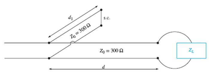
Chapter 10, Problem 10.34P
The lossless line shown in Figure 10.35 is operating with
Expert Solution & Answer
Want to see the full answer?
Check out a sample textbook solution
Students have asked these similar questions
Assume the saturation mode and solve for the Q point. Find VGSQ, IDQ, and VDSQ. Given VTN = 1.0 V and Kn = 2 mA/V^2
Could you please go more in depth about how to create the ac equivalant model? thank you
During the first month of work, you get an assignment to perform a measurement campaign to estimate the channel path loss exponent for a new wireless product. You performed field measurements and collected the following data: Reference path loss: PL(d0) Path loss measurements: PL (d1), PL (d2), ... PL (dn), at distances d1 … dn Using the path loss exponent model, find an expression for the optimum value of the path loss exponent n, which minimizes the mean square error between measurements and the model. Hint: the optimum value of n should minimize the mean square error (MSE) between your predicted path loss and measured path loss.
Chapter 10 Solutions
Engineering Electromagnetics
Ch. 10 - The parameters of a certain transmission line...Ch. 10 - A sinusoidal wave on a transmission line is...Ch. 10 - Prob. 10.3PCh. 10 - A sinusoidal voltage V0, frequency , and phase...Ch. 10 - Two voltage waves of equal amplitude V0 and radian...Ch. 10 - A 50 load is attached to a 50-m section of the...Ch. 10 - Prob. 10.7PCh. 10 - An absolute measure of power is the dBm scale, in...Ch. 10 - A 100-m transmission line is used to propagate a...Ch. 10 - Two lossless transmission lines having different...
Ch. 10 - Two voltage waves of equal amplitude V0, which...Ch. 10 - In a circuit in which a sinusoidal voltage source...Ch. 10 - The skin effect mechanism in transmission lines is...Ch. 10 - A lossless transmission line having characteristic...Ch. 10 - Figure 10.29 See Problem 10.15. For the...Ch. 10 - A 100 lossless transmission line is connected to a...Ch. 10 - Determine the average power absorbed by each...Ch. 10 - The line shown in Figure 10.31 is lossless. Find s...Ch. 10 - A lossless transmission line is 50 cm in length...Ch. 10 - (a) Determine s on the transmission line of Figure...Ch. 10 - Prob. 10.21PCh. 10 - Prob. 10.22PCh. 10 - The normalized load on a lossless transmission...Ch. 10 - Prob. 10.24PCh. 10 - Prob. 10.25PCh. 10 - A 75 lossless line is of length 1.2 . It is...Ch. 10 - Prob. 10.27PCh. 10 - The wavelength on a certain lossless line is 10...Ch. 10 - Prob. 10.29PCh. 10 - A two-wire line constructed of lossless wire of...Ch. 10 - In order to compare the relative sharpness of the...Ch. 10 - In Figure 10.17, let ZL=250 and Z0=50. Find the...Ch. 10 - In Figure 10.17, let ZL=100+j150 and Z0=100. Find...Ch. 10 - The lossless line shown in Figure 10.35 is...Ch. 10 - Prob. 10.35PCh. 10 - The two-wire lines shown in Figure 10.36 are all...Ch. 10 - Prob. 10.37PCh. 10 - Repeat Problem 10.37, with, Z0=50 and RL=Rg=25....Ch. 10 - In the transmission line of Figure 10.20, Z0=50,...Ch. 10 - In the charged line of Figure 10.25, the...Ch. 10 - In the transmission line of Figure 10.37, the...Ch. 10 - Figure 10.38 See Problem 10.42. A simple frozen...Ch. 10 - Figure 10.39 See Problem 10.43. In Figure 10.39,...
Knowledge Booster


Learn more about
Need a deep-dive on the concept behind this application? Look no further. Learn more about this topic, electrical-engineering and related others by exploring similar questions and additional content below.Similar questions
- A 2 V signal is incident to the interface from a 75 Ohm region propagating to a 50 Ohm impedance region. What is the reflection coefficient? What is value of the incident, reflected and transmitted wave? What voltage would you measure on either side of the interface right after the signal goes through the interface. For the interface, I'm a little confused. I used a voltage divider and got V_transmitted = 0.8 and V_incident = 1.2. But shouldn't they be the same?arrow_forwardQuiz:Sketch the general shape' of the root locus for each of the open- loop pole -Zero plots shown in the figure.cuse oll necessary calculations) jw (a) (b) s-plane s-plane two poles jw splane (d) (C) A jw (e) s-planearrow_forwardThe period of this signal is about------ ms (milliseconds). The oscilloscope range selector determines the scale on the screen. That means number of volts per line for amplitude vertical (v/div) and the number of milliseconds per line for time horizontally (ms/div).arrow_forward
- b) If quantity A is PATAT with TC of 2mV/C, and quantity B is CTAT with TC of -1mVrC, then determine the following quantities if they are PTAT or CTAT 1. 1/A 2. 1/B 3. A+ 5°Barrow_forwardWhat does the TE mean? Why does one have a 10 as subscript and the other mn? What is a broad and short dimension and a rectangular waveguide?arrow_forwardProblem 4 - Consider the line spectrum below. The vertical units are volts. 3 -3MHz -4MHz -j2 (a) What is the total power? j2 3 3MHz 4MHz f (b) Find the corresponding time domain signal x(1).arrow_forward
- An unmodulated carrier is 680 Vp-p. Calculate the %m when its maximum p-p value reaches 650, 850 and 1050 V, and the minimum p-p value reaches 500, 300 and 50 V, respectively, upon modulation.arrow_forward3. Coaxial cable is used in applications requiring the propagation of high-frequency signal. Such cable consists of a solid conducting cylinder as the inner conductor and a solid conducting cylindrical shell as the outer conductor. A dielectric fills the region between these conductors. Consider the RG-59/U coaxial cable that is commonly used to connect a television/internet equipment. It has an inner conductor with a diameter of 0.584 mm, dielectric filler with a dielectric constant of K = 1.20, and an outer conductor with an inner diameter of 3.7084 mm. Assuming that these conductors are very long, calculate the capacitance per metre of the RG-59/U coaxial cable. Include a derivation of an equation for the capacitance per unit length of the coaxial cable and then use this equation to calculate your answer. (As discussed in class, assign a charge +Q and voltage V to the inner conductor and a charge -Q and 0 V to the outer conductor, solve for the voltage V, and then compute the…arrow_forward4. Again, from the zigzag-path waveguiding model, explain why the group velocity is always slower than the phase velocity in a waveguide with a cutoff frequency.arrow_forward
- (1 - FIT) = (1 - FIS) x (1 - FST) . true or false (1 - HT) = (1 - HI) x (1 - HS) . true or false HS + HT + HI = 1. True or false FIT = FIS + FST. True or false..arrow_forward• Create an instance of Qm/prmp/Cmax with at least 3 jobs and 2 machines (at different speeds). Apply LRPT-FM rule and show the resulting schedule on a Gannt chart.arrow_forwardI need help with the MATLAB section, please.arrow_forward
arrow_back_ios
SEE MORE QUESTIONS
arrow_forward_ios
Recommended textbooks for you
 Introductory Circuit Analysis (13th Edition)Electrical EngineeringISBN:9780133923605Author:Robert L. BoylestadPublisher:PEARSON
 Delmar's Standard Textbook Of ElectricityElectrical EngineeringISBN:9781337900348Author:Stephen L. HermanPublisher:Cengage Learning
 Programmable Logic ControllersElectrical EngineeringISBN:9780073373843Author:Frank D. PetruzellaPublisher:McGraw-Hill Education
 Fundamentals of Electric CircuitsElectrical EngineeringISBN:9780078028229Author:Charles K Alexander, Matthew SadikuPublisher:McGraw-Hill Education
 Electric Circuits. (11th Edition)Electrical EngineeringISBN:9780134746968Author:James W. Nilsson, Susan RiedelPublisher:PEARSON
 Engineering ElectromagneticsElectrical EngineeringISBN:9780078028151Author:Hayt, William H. (william Hart), Jr, BUCK, John A.Publisher:Mcgraw-hill Education,
Introductory Circuit Analysis (13th Edition)
Electrical Engineering
ISBN:9780133923605
Author:Robert L. Boylestad
Publisher:PEARSON
Delmar's Standard Textbook Of Electricity
Electrical Engineering
ISBN:9781337900348
Author:Stephen L. Herman
Publisher:Cengage Learning
Programmable Logic Controllers
Electrical Engineering
ISBN:9780073373843
Author:Frank D. Petruzella
Publisher:McGraw-Hill Education
Fundamentals of Electric Circuits
Electrical Engineering
ISBN:9780078028229
Author:Charles K Alexander, Matthew Sadiku
Publisher:McGraw-Hill Education
Electric Circuits. (11th Edition)
Electrical Engineering
ISBN:9780134746968
Author:James W. Nilsson, Susan Riedel
Publisher:PEARSON
Engineering Electromagnetics
Electrical Engineering
ISBN:9780078028151
Author:Hayt, William H. (william Hart), Jr, BUCK, John A.
Publisher:Mcgraw-hill Education,
How does an Antenna work? | ICT #4; Author: Lesics;https://www.youtube.com/watch?v=ZaXm6wau-jc;License: Standard Youtube License