
Concept explainers
Videos
The skin effect
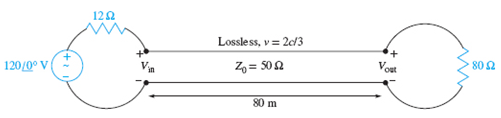
Figure 10.29 See Problem 10.15.
Want to see the full answer?
Check out a sample textbook solution
Chapter 10 Solutions
Engineering Electromagnetics


- The 50 ohm transmission line isterminated with an unknown load. The magnitude of the reflection coefficient is R=0.5.Thedistancebetween the voltage maximum and the load is0.15 lambda. What is the imaginary partof the load impedance?arrow_forward1. a. A purely reactive load impedance Z₁ =jX terminates a transmission line. Prove that the reflection coefficient magnitude |K| is always unity, assuming the characteristic impedance Zo is real. What is the VSWR of the line in this case? b. Consider the transmission line in the figure. i. Determine the SWR on transmission line ii. The input impedance If=102, find I, in the figure. WC 100/0*V] 20 922 Air, lossless Z-50 £2 2.72 40 2 ele 3002arrow_forwardA single-phase transmission line consisting of two conductors, the radius of each conductor is 0.4 cm, the distance between the conductors is three and half meters and the height above ground is eight meter. Determine 1)The capacitance in uF/km without effect of ground 2)The capacitance in uF/km with effect of groundarrow_forward
- A distortionless transmission line has a resistance per unit length of 0.5 ohm/m. If the characteristic impedance of the line is 50 ohm, them what will be the attenuation constant of the line in Neper (Np)/m?arrow_forwardA Parallel wire line has its radius of the conductor is 0.2 mm and the distance between the conductors is 0.55 inches. Compute for the characteristic impedance of the line.arrow_forward4. (a) A transmission line with a characteristic impedance of 100 has a load of 1 k2 resistance in parallel with a 0.005 µF capacitor connected across the far end. A surge voltage of magnitude 10 kV and unit function form (i.e. step function) travels along the line. Derive an expression for the time variation of the voltage across the load, and calculate the value of this voltage 10us after the arrival of the wave front of the surgearrow_forward
- The measurement made on a transmission line is given by the graphic in the figure. If the line length is 8.4 cm and characteristic impedance is 50 ohms; Find the load reflection coefficient, load impedance, reflection coefficient at the line input.arrow_forwardThe char. impedance of the trans. line is 50-Ohm and the resistance of it is 0.1Ohm/meter. What will be the value of the attenuation constant when the line is distortion less?arrow_forwardDiscuss the methods used to minimize inductance in transmission lines and their effects on signal transmission.arrow_forward
- Over string of three phase transmission line has a four insulators and Ce=D0.12 C. If the voltage between the steal pin of the first insulator and the metal cap of the third insulator is 33 kv. 1- Find the voltage distribution over the insulator. What will be the string efficiency 2- If the sting is supplied by a guard ring and this lead to add one air capacitance of value 0.2 C. What will be the new distribution over the insulators and what will be the new string efficiency.arrow_forwardSolve this math : A three-phase 60-hz transmission line has its conductors arranged in a triangular formation so that two of the distances between conductors are 20ft and the third is 40 ft. The conductors are ACSR Rook. Determine the capacitance to neutral in microfarads per mile and the capacitive reactance to neutral in ohm-miles. If the line is 115 mi long, find the capacitance to neutral and capacitive reactance of the line. Note: In the below i have added similer type of math and its ans.In the above math, there is just changes of values and Main Change is ACSR ROOK which is given to then question and in the below question which is solved it was ask ACSR Parakeet. So notice that. Follow This Book for help"POWER SYSTEM ANALYSISAND DESIGN;FIFTH EDITION, SI;J. DUNCAN GLOVER" Now solve the math according to the given way solve the math. "A three-phase 60-hz transmission line has its conductors arranged in a triangular formation so that two of the distances between conductors are 25…arrow_forwardEach phase of a transmission line is a bundle of 4 conductors that form a square with all sides equal to d=33 cm. Each conductor is stranded and has GMR = 0.5 cm. Find GMR of the bundle to be used in inductance calculations. Express your answer in cm with 2 digits after decimal pointarrow_forward
 Introductory Circuit Analysis (13th Edition)Electrical EngineeringISBN:9780133923605Author:Robert L. BoylestadPublisher:PEARSON
 Delmar's Standard Textbook Of ElectricityElectrical EngineeringISBN:9781337900348Author:Stephen L. HermanPublisher:Cengage Learning
 Programmable Logic ControllersElectrical EngineeringISBN:9780073373843Author:Frank D. PetruzellaPublisher:McGraw-Hill Education
 Fundamentals of Electric CircuitsElectrical EngineeringISBN:9780078028229Author:Charles K Alexander, Matthew SadikuPublisher:McGraw-Hill Education
 Electric Circuits. (11th Edition)Electrical EngineeringISBN:9780134746968Author:James W. Nilsson, Susan RiedelPublisher:PEARSON
 Engineering ElectromagneticsElectrical EngineeringISBN:9780078028151Author:Hayt, William H. (william Hart), Jr, BUCK, John A.Publisher:Mcgraw-hill Education,