
Electronics Fundamentals: Circuits, Devices & Applications
8th Edition
ISBN: 9780135072950
Author: Thomas L. Floyd, David Buchla
Publisher: Prentice Hall
expand_more
expand_more
format_list_bulleted
Concept explainers
Videos
Textbook Question
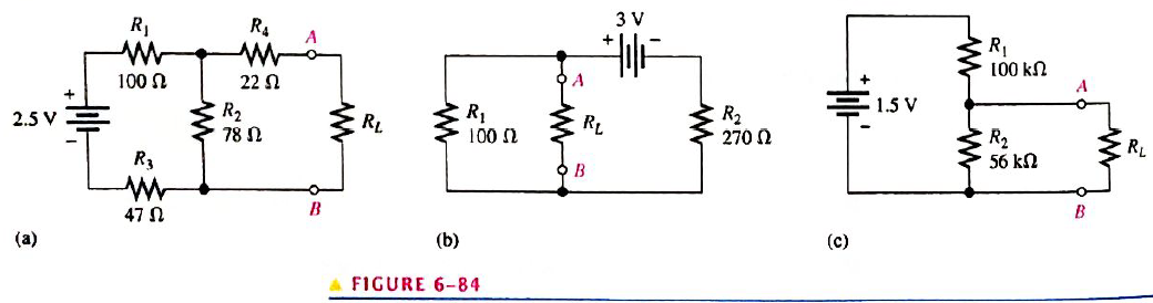
Chapter 6, Problem 28P
For each circuit in Figure 6-84, determine the Thevenin equivalent as seen from terminals A and B.
 s
s
Expert Solution & Answer
Want to see the full answer?
Check out a sample textbook solution
Students have asked these similar questions
6. When using superposition, what is the ideal
internal resistance of a current source?
Short circuit
The source voltage divided by the source
resistance
The source voltage divided by the load
resistance
Infinite resistance
the source current through R1 is 6.34 mA. use current divider to determine how much current goes through R5 and R6
6 cells with 2 V emf and 0.1ohm internal resistance are connected in series. Four such sets are connected in parallel. The entire circuit is connected to a 9.85 ohm load. So find the load current, the current through each cell and the load voltage.
Chapter 6 Solutions
Electronics Fundamentals: Circuits, Devices & Applications
Ch. 6 - Parallel resistors are always connected between...Ch. 6 - If one resistor is connected in series with a...Ch. 6 - In a series-parallel combinational circuit, the...Ch. 6 - A larger load resistor has a smaller loading...Ch. 6 - When measuring de voltage, a DMM will normally...Ch. 6 - When measuring de voltage, the input resistance of...Ch. 6 - When measuring & voltage, the input resistance of...Ch. 6 - A Thevenin circuit consists of a voltage source...Ch. 6 - The internal resistance of an ideal voltage source...Ch. 6 - To transfer maximum power to a load, the load...
Ch. 6 - Which of the following statements are true...Ch. 6 - The total resistance of Figure 6-73 can be found...Ch. 6 - If all of the resistors in Figure 6-73 have the...Ch. 6 - Prob. 4STCh. 6 - The parallel combination of a 330 resistor and a...Ch. 6 - In the circuit described in Question 5, the...Ch. 6 - Prob. 7STCh. 6 - The output of a certain voltage divider is 9V with...Ch. 6 - Prob. 9STCh. 6 - When a load resistance is connected to the output...Ch. 6 - The output voltage of a balanced Wheatstone bridge...Ch. 6 - Prob. 12STCh. 6 - In a certain two-source circuit, one source acting...Ch. 6 - Prob. 14STCh. 6 - Prob. 15STCh. 6 - You are measuring the voltage at a given point in...Ch. 6 - Prob. 1TSCCh. 6 - Determine the cause for each set of symtims. Refer...Ch. 6 - Prob. 3TSCCh. 6 - Determine the cause for each set of symptoms....Ch. 6 - Prob. 5TSCCh. 6 - Identify the series and parallel relationships in...Ch. 6 - Visualize and draw the following series-parallel...Ch. 6 - Visualize and draw the following series-parallel...Ch. 6 - In each circuit of Figure 6-76 identify the series...Ch. 6 - A certain circuit is composed of two parallel...Ch. 6 - For the circuit in Figure 6-77, determine the...Ch. 6 - Determine the total resistance for each circuit in...Ch. 6 - Determine the current through each resistor in...Ch. 6 - Determine the current through each resistor in...Ch. 6 - In Figure 6-78, find the following: total...Ch. 6 - In Figure 6-78, determine the current through R2...Ch. 6 - In Figure 6-78, determine the current through R4...Ch. 6 - A vlotage divider consists of two 56k resistors...Ch. 6 - A 12 V battery output is divided down to obtain...Ch. 6 - Which will cause a smaller decrease in output...Ch. 6 - In Figure 6-79, determine the current drain on the...Ch. 6 - Across which one of the following resistances will...Ch. 6 - A certain voltage divider consists of three 1.0M...Ch. 6 - What is the difference between the measured and...Ch. 6 - By what percentage does the voltmeter in Problem...Ch. 6 - A 10,000/VVOM is used on the 10 V scale to measure...Ch. 6 - If a DMM with 10M input resistance is used instead...Ch. 6 - A resistor of unknown value is connected to a...Ch. 6 - A bridge network is shown In Figure 6-80. To what...Ch. 6 - Determine the value of RX in the balance bridge in...Ch. 6 - Determine the outpur voltage of the unbalanced...Ch. 6 - Reduce the circuit in Figure 6-83 to its Thevenin...Ch. 6 - For each circuit in Figure 6-84, determine the...Ch. 6 - Determine the voltage and current for R1 in Figure...Ch. 6 - Determin the value of a load resistor connected...Ch. 6 - A certain Thevenin equivalent circuit has a...Ch. 6 - Determine the value of RL in Figure 6-84(a) for...Ch. 6 - In Figure 6-86, use ther superposition therorem to...Ch. 6 - In Figure 6-86, What is the curent through R2?...Ch. 6 - Is the voltmeter reading in Figure 6-87 correct?...Ch. 6 - If R2 in Figure 6-88 opens, what voltages will be...Ch. 6 - Check the meter readings in Figure 6-89 and locate...Ch. 6 - Determine the voltage you would expect to measure...Ch. 6 - Determine the voltage you would expect to measure...Ch. 6 - In each circuit of Figure 6-90, identify the...Ch. 6 - Draw the schematic of the PC board layout in...Ch. 6 - 1For the circuit shown in Figure 6-92, calculate...Ch. 6 - Determine the total resistance and the voltage at...Ch. 6 - Determine the total resistance between terminals A...Ch. 6 - What is the voltage across each resistor in Figure...Ch. 6 - Determine the voltage, VAB. in Figure 6-95. FIGURE...Ch. 6 - Find the value of R2 in Figure 6-96. FIGURE 6-96Ch. 6 - Determine the total resistance and the voltage at...Ch. 6 - Develop a voltage divider to provide a 6 V output...Ch. 6 - Determine the resistance values for a voltage...Ch. 6 - Using the superposition therorem, calculate the...Ch. 6 - Find the current through RL in Figure 6-99. FIGURE...Ch. 6 - Using Thevenin’s theorem, find the voltage...Ch. 6 - Determine VOUT for the circuit in Figure 6-101 for...Ch. 6 - Develop a schematic for the double-sided PC board...Ch. 6 - Lay out a PC board for the circuit in Figure...Ch. 6 - The voltage divider in Figure 6-103 has a switched...Ch. 6 - Figure 6-104 shows a dc biasing arrangement for a...Ch. 6 - Look at the voltmeters in Figure 6-105 and...Ch. 6 - Are the voltmeter reading in Figure 6-106 correct?...Ch. 6 - There is one fault in Figure 6-107. Bases on the...Ch. 6 - Look at the voltmeters in Figure 6-108 and...Ch. 6 - Determine the voltmeter reading in Figure 6-108 if...Ch. 6 - Open file P06-64; files are found at...Ch. 6 - www.prenhall.com/floyd. 65. Open file P06-65 and...Ch. 6 - www.prenhall.com/floyd. 66. Open file P06-66 and...Ch. 6 - www.prenhall.com/floyd. 67. Open file P06-67 and...Ch. 6 - www.prenhall.com/floyd. 68. Open file P06-68 and...Ch. 6 - www.prenhall.com/floyd. 69. Open file P06-69 and...Ch. 6 - www.prenhall.com/floyd. 70. Open file P06-70 and...Ch. 6 - www.prenhall.com/floyd. 71. Open file P06-71 and...
Knowledge Booster


Learn more about
Need a deep-dive on the concept behind this application? Look no further. Learn more about this topic, electrical-engineering and related others by exploring similar questions and additional content below.Similar questions
- 28. For the multiplexer in Figure 6-79, determine the output for the following input states: D₁ = 0, D₁ = 1, D₂ = 1, D3 = 0, S₁ = 1, S₁ = 0. So S₁ Do D₁ D₂ D3 MUX } of G 0 1 2 3 Figure 6-79 Yarrow_forwardIn Figure 6-85 , use the superposition theorem to find the current in R3 and what is the current through R2 ?arrow_forward14. For the 4-bit comparator in Figure 6–74, plot each output waveform for the inputs shown. The outputs are active-HIGH. Ao СOMP Ao A1 A A2. A2 A3 A3 A> B A>B Vcc A = B Aarrow_forwardDetermine the value of a load resistor connected between terminals A and B in Figure 6-82 for maximum power transfer to the load resistor.arrow_forward1. Four 0.5 A current sources are connected in parallel in the same direction. What current will be produced through a load resistor? 2. How many 100 mA current sources must be connected in parallel to produce a total current output of 300 mA? Draw a schematic showing the sources connected. 3. In a certain transistor amplifier circuit, the transistor can be represented by a 10 mA current source, as shown in Figure 6-31. In a certain transistor amplifier, two transis- tors act in parallel. How much current is there through the resistor Re? » FIGURE 6-31 D10 mA D10 mA RE 1.0 karrow_forwardcan someone show me how to do this problem step by step please a device can be modeled as a current source in parallell wih a resistancearrow_forwardCalculate RT for each circuit in Figure 6–66.arrow_forwardObtain the equivalent resistance at the terminals a-b for each of the circuits using delta to y or star or botharrow_forward6- What is the total resistance of the mixed circuits shown in the following Figure? Note that each resistor has resistance 6.00. (a) R₁ R₁ R₂ R3 R₁ (b) R₁ Em سره سره R₂ R3 R₁ R₂ Emarrow_forwardDetermine the output voltage of the unbalanced bridge in Figure 6-81 for a temperature of 65°C. The thermistor has a nominal resistance of 1 k2 at 25°C and a positive temperature coef- ficient. Assume that its resistance changes 5 for each C° change in temperature. R₁ Thermistor R3 1.0 ΚΩ +9 V B3 VOO R₂ 1.0 ΚΩ R4 1.0 ΚΩ FIGURE 6-81arrow_forwardReduce the circuit to a single current source with a resistor in parallelarrow_forwardA RL series has two resistors and two inductors. The Z of the circuit is 1000 ohms. The XL of the inductors is 220 ohms and 470 ohms. one of the resistors has a resistance of 300 ohms. What is the resistance of the other resistor?arrow_forwardarrow_back_iosSEE MORE QUESTIONSarrow_forward_ios
Recommended textbooks for you
 Electricity for Refrigeration, Heating, and Air C...Mechanical EngineeringISBN:9781337399128Author:Russell E. SmithPublisher:Cengage Learning
Electricity for Refrigeration, Heating, and Air C...
Mechanical Engineering
ISBN:9781337399128
Author:Russell E. Smith
Publisher:Cengage Learning
What is an electric furnace and how does it work?; Author: Fire & Ice Heating and Air Conditioning Inc;https://www.youtube.com/watch?v=wjAWecPGi0M;License: Standard Youtube License