
Electronics Fundamentals: Circuits, Devices & Applications
8th Edition
ISBN: 9780135072950
Author: Thomas L. Floyd, David Buchla
Publisher: Prentice Hall
expand_more
expand_more
format_list_bulleted
Videos
Textbook Question
Chapter 6, Problem 25P
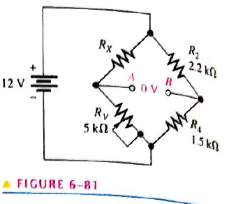
Determine the value of
Expert Solution & Answer
Want to see the full answer?
Check out a sample textbook solution
Students have asked these similar questions
SA
[(a) 5 V (b) 5 V]
13. Find the voltage V in the network shown in Fig. 2.44 (a) if R is 10 2 and (b) 20 2
14. In the network of Fig. 2.44 (b), calculate the voltage between points a and b i.e. Vab
[30 V] (Elect. Engg. I, Bombay Univ.)
4A
78A
4
h
10A
ww
3A
(a)
ΤΑ
6A
DC Network Theorems
SA
Is
1A
77
12A
www
12
6A
8A
Fig. 2.44
(b)
[Hint: In the above two cases, the two closed loops are independent and no current passes between them].
Need a sol
Don't use ai to answer I will report you answer
Chapter 6 Solutions
Electronics Fundamentals: Circuits, Devices & Applications
Ch. 6 - Parallel resistors are always connected between...Ch. 6 - If one resistor is connected in series with a...Ch. 6 - In a series-parallel combinational circuit, the...Ch. 6 - A larger load resistor has a smaller loading...Ch. 6 - When measuring de voltage, a DMM will normally...Ch. 6 - When measuring de voltage, the input resistance of...Ch. 6 - When measuring & voltage, the input resistance of...Ch. 6 - A Thevenin circuit consists of a voltage source...Ch. 6 - The internal resistance of an ideal voltage source...Ch. 6 - To transfer maximum power to a load, the load...
Ch. 6 - Which of the following statements are true...Ch. 6 - The total resistance of Figure 6-73 can be found...Ch. 6 - If all of the resistors in Figure 6-73 have the...Ch. 6 - Prob. 4STCh. 6 - The parallel combination of a 330 resistor and a...Ch. 6 - In the circuit described in Question 5, the...Ch. 6 - Prob. 7STCh. 6 - The output of a certain voltage divider is 9V with...Ch. 6 - Prob. 9STCh. 6 - When a load resistance is connected to the output...Ch. 6 - The output voltage of a balanced Wheatstone bridge...Ch. 6 - Prob. 12STCh. 6 - In a certain two-source circuit, one source acting...Ch. 6 - Prob. 14STCh. 6 - Prob. 15STCh. 6 - You are measuring the voltage at a given point in...Ch. 6 - Prob. 1TSCCh. 6 - Determine the cause for each set of symtims. Refer...Ch. 6 - Prob. 3TSCCh. 6 - Determine the cause for each set of symptoms....Ch. 6 - Prob. 5TSCCh. 6 - Identify the series and parallel relationships in...Ch. 6 - Visualize and draw the following series-parallel...Ch. 6 - Visualize and draw the following series-parallel...Ch. 6 - In each circuit of Figure 6-76 identify the series...Ch. 6 - A certain circuit is composed of two parallel...Ch. 6 - For the circuit in Figure 6-77, determine the...Ch. 6 - Determine the total resistance for each circuit in...Ch. 6 - Determine the current through each resistor in...Ch. 6 - Determine the current through each resistor in...Ch. 6 - In Figure 6-78, find the following: total...Ch. 6 - In Figure 6-78, determine the current through R2...Ch. 6 - In Figure 6-78, determine the current through R4...Ch. 6 - A vlotage divider consists of two 56k resistors...Ch. 6 - A 12 V battery output is divided down to obtain...Ch. 6 - Which will cause a smaller decrease in output...Ch. 6 - In Figure 6-79, determine the current drain on the...Ch. 6 - Across which one of the following resistances will...Ch. 6 - A certain voltage divider consists of three 1.0M...Ch. 6 - What is the difference between the measured and...Ch. 6 - By what percentage does the voltmeter in Problem...Ch. 6 - A 10,000/VVOM is used on the 10 V scale to measure...Ch. 6 - If a DMM with 10M input resistance is used instead...Ch. 6 - A resistor of unknown value is connected to a...Ch. 6 - A bridge network is shown In Figure 6-80. To what...Ch. 6 - Determine the value of RX in the balance bridge in...Ch. 6 - Determine the outpur voltage of the unbalanced...Ch. 6 - Reduce the circuit in Figure 6-83 to its Thevenin...Ch. 6 - For each circuit in Figure 6-84, determine the...Ch. 6 - Determine the voltage and current for R1 in Figure...Ch. 6 - Determin the value of a load resistor connected...Ch. 6 - A certain Thevenin equivalent circuit has a...Ch. 6 - Determine the value of RL in Figure 6-84(a) for...Ch. 6 - In Figure 6-86, use ther superposition therorem to...Ch. 6 - In Figure 6-86, What is the curent through R2?...Ch. 6 - Is the voltmeter reading in Figure 6-87 correct?...Ch. 6 - If R2 in Figure 6-88 opens, what voltages will be...Ch. 6 - Check the meter readings in Figure 6-89 and locate...Ch. 6 - Determine the voltage you would expect to measure...Ch. 6 - Determine the voltage you would expect to measure...Ch. 6 - In each circuit of Figure 6-90, identify the...Ch. 6 - Draw the schematic of the PC board layout in...Ch. 6 - 1For the circuit shown in Figure 6-92, calculate...Ch. 6 - Determine the total resistance and the voltage at...Ch. 6 - Determine the total resistance between terminals A...Ch. 6 - What is the voltage across each resistor in Figure...Ch. 6 - Determine the voltage, VAB. in Figure 6-95. FIGURE...Ch. 6 - Find the value of R2 in Figure 6-96. FIGURE 6-96Ch. 6 - Determine the total resistance and the voltage at...Ch. 6 - Develop a voltage divider to provide a 6 V output...Ch. 6 - Determine the resistance values for a voltage...Ch. 6 - Using the superposition therorem, calculate the...Ch. 6 - Find the current through RL in Figure 6-99. FIGURE...Ch. 6 - Using Thevenin’s theorem, find the voltage...Ch. 6 - Determine VOUT for the circuit in Figure 6-101 for...Ch. 6 - Develop a schematic for the double-sided PC board...Ch. 6 - Lay out a PC board for the circuit in Figure...Ch. 6 - The voltage divider in Figure 6-103 has a switched...Ch. 6 - Figure 6-104 shows a dc biasing arrangement for a...Ch. 6 - Look at the voltmeters in Figure 6-105 and...Ch. 6 - Are the voltmeter reading in Figure 6-106 correct?...Ch. 6 - There is one fault in Figure 6-107. Bases on the...Ch. 6 - Look at the voltmeters in Figure 6-108 and...Ch. 6 - Determine the voltmeter reading in Figure 6-108 if...Ch. 6 - Open file P06-64; files are found at...Ch. 6 - www.prenhall.com/floyd. 65. Open file P06-65 and...Ch. 6 - www.prenhall.com/floyd. 66. Open file P06-66 and...Ch. 6 - www.prenhall.com/floyd. 67. Open file P06-67 and...Ch. 6 - www.prenhall.com/floyd. 68. Open file P06-68 and...Ch. 6 - www.prenhall.com/floyd. 69. Open file P06-69 and...Ch. 6 - www.prenhall.com/floyd. 70. Open file P06-70 and...Ch. 6 - www.prenhall.com/floyd. 71. Open file P06-71 and...
Knowledge Booster


Learn more about
Need a deep-dive on the concept behind this application? Look no further. Learn more about this topic, electrical-engineering and related others by exploring similar questions and additional content below.Similar questions
- They are one quearrow_forwardO Draw the four possible negative feedback contigurations of an op-amp. Write the input and output impedances of these configurations in ideal cases. 5arrow_forwardE9.6 Determine the average power absorbed by the 4-2 and 3-2 resistors in Fig. E9.6. 302 j20 Figure E9.3 4Ω ww Figure E9.6 12/0° V j30 -j2 N 13/10° A (+60° V (OEFarrow_forward
- -160 For the P-channel JFET given in the following figure, the IDSS = 2MA a) Determine IDQ and VSDQ b) Determine the source-follower circuit transistor parameters are: Vp = +1,75 V, and λ=0. Small-signal voltage gain, Av = So VDD = 10V R₁ = 90kr Rs =5k CC1 WW R₂ = 110kn 50 C02 BL = 10 kr GNDarrow_forwardNeed a solarrow_forwardI need a drawing on how to connect the function generator, oscilliscope, and both multimeters. It is hard for me to follow text instructions. The function generator has a postive,common and negative. The oscilliscope has chanell A and B, both channels have a postive and a negative. I know you can provide text instruction but a little sketch would be very helpful thank you.arrow_forward
- Don't use ai to answer I will report you answerarrow_forwardQ1/ A three phase, 500 kVA, 6600 V, 50 Hz, 6 pole, star connected synchronous motor has synchronous impedance of J 70 ohm per phase at its normal rating, the motor is excited to give unity power factor at the input terminals. Find a) The rated current and power factor. b) The emf behind the synchronous impedance. c) The developed torque. d) The pull out torque. e) The increase in excitation which will just permit an increase of 30% of rated torque before pulling out of synchronism. (45 M.)arrow_forwardcan you fin Vds and Vgs of all transistors and specify te operating region off all transistors and prove it. 58V 5.8 V 1.8V M2 0.9V 22222 と A 4852 m 3 01 A Voy = 0.2 V V4)=0.SV λ=0.1 V-1arrow_forward
arrow_back_ios
SEE MORE QUESTIONS
arrow_forward_ios
Recommended textbooks for you
 Electricity for Refrigeration, Heating, and Air C...Mechanical EngineeringISBN:9781337399128Author:Russell E. SmithPublisher:Cengage Learning
 Delmar's Standard Textbook Of ElectricityElectrical EngineeringISBN:9781337900348Author:Stephen L. HermanPublisher:Cengage Learning
Electricity for Refrigeration, Heating, and Air C...
Mechanical Engineering
ISBN:9781337399128
Author:Russell E. Smith
Publisher:Cengage Learning
Delmar's Standard Textbook Of Electricity
Electrical Engineering
ISBN:9781337900348
Author:Stephen L. Herman
Publisher:Cengage Learning
Pressure Sensors with Display; Author: Balluff Worldwide;https://www.youtube.com/watch?v=HqAV2xjCLxE;License: Standard Youtube License