
Electronics Fundamentals: Circuits, Devices & Applications
8th Edition
ISBN: 9780135072950
Author: Thomas L. Floyd, David Buchla
Publisher: Prentice Hall
expand_more
expand_more
format_list_bulleted
Concept explainers
Videos
Textbook Question
Chapter 6, Problem 33P
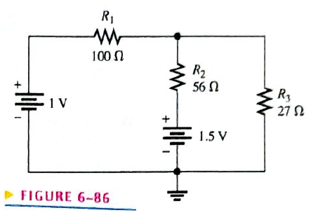
In Figure 6-86, use ther superposition therorem to find the current in
Figure 6-86
Expert Solution & Answer
Want to see the full answer?
Check out a sample textbook solution
Students have asked these similar questions
the source current through R1 is 6.34 mA. use current divider to determine how much current goes through R5 and R6
4. For the parallel adder in Figure 6-69, determine the complete sum by analysis of the logical
operation of the circuit. Verify your result by longhand addition of the two input numbers.
Figure 6-69
Figure 6-70
1 0
A B Cin
Cout
Σε
Σ
A B Cin
Σε
Cout
ΣΑ
Σ
5. Repeat Problem 4 for the circuit and input conditions in Figure 6-70.
Ο Ο
A B Cin
Cout Σ
1 0
ΣΑ
A B Cin|
Cout Σ
A B Cin
Cout
Σ
A B C
Σ;
Cout
Σ
0 1
Σ
A B Cin
Cout Σ
Στ
A B Cin
Cout
Σ
Reduce the circuit in Figure 6-82 to its Thevenin equivalent as viewed from terminals A and B.
15 V
FIGURE 6-82
R₁
100 ΚΩ
R₂
22 ΚΩ
OB
Chapter 6 Solutions
Electronics Fundamentals: Circuits, Devices & Applications
Ch. 6 - Parallel resistors are always connected between...Ch. 6 - If one resistor is connected in series with a...Ch. 6 - In a series-parallel combinational circuit, the...Ch. 6 - A larger load resistor has a smaller loading...Ch. 6 - When measuring de voltage, a DMM will normally...Ch. 6 - When measuring de voltage, the input resistance of...Ch. 6 - When measuring & voltage, the input resistance of...Ch. 6 - A Thevenin circuit consists of a voltage source...Ch. 6 - The internal resistance of an ideal voltage source...Ch. 6 - To transfer maximum power to a load, the load...
Ch. 6 - Which of the following statements are true...Ch. 6 - The total resistance of Figure 6-73 can be found...Ch. 6 - If all of the resistors in Figure 6-73 have the...Ch. 6 - Prob. 4STCh. 6 - The parallel combination of a 330 resistor and a...Ch. 6 - In the circuit described in Question 5, the...Ch. 6 - Prob. 7STCh. 6 - The output of a certain voltage divider is 9V with...Ch. 6 - Prob. 9STCh. 6 - When a load resistance is connected to the output...Ch. 6 - The output voltage of a balanced Wheatstone bridge...Ch. 6 - Prob. 12STCh. 6 - In a certain two-source circuit, one source acting...Ch. 6 - Prob. 14STCh. 6 - Prob. 15STCh. 6 - You are measuring the voltage at a given point in...Ch. 6 - Prob. 1TSCCh. 6 - Determine the cause for each set of symtims. Refer...Ch. 6 - Prob. 3TSCCh. 6 - Determine the cause for each set of symptoms....Ch. 6 - Prob. 5TSCCh. 6 - Identify the series and parallel relationships in...Ch. 6 - Visualize and draw the following series-parallel...Ch. 6 - Visualize and draw the following series-parallel...Ch. 6 - In each circuit of Figure 6-76 identify the series...Ch. 6 - A certain circuit is composed of two parallel...Ch. 6 - For the circuit in Figure 6-77, determine the...Ch. 6 - Determine the total resistance for each circuit in...Ch. 6 - Determine the current through each resistor in...Ch. 6 - Determine the current through each resistor in...Ch. 6 - In Figure 6-78, find the following: total...Ch. 6 - In Figure 6-78, determine the current through R2...Ch. 6 - In Figure 6-78, determine the current through R4...Ch. 6 - A vlotage divider consists of two 56k resistors...Ch. 6 - A 12 V battery output is divided down to obtain...Ch. 6 - Which will cause a smaller decrease in output...Ch. 6 - In Figure 6-79, determine the current drain on the...Ch. 6 - Across which one of the following resistances will...Ch. 6 - A certain voltage divider consists of three 1.0M...Ch. 6 - What is the difference between the measured and...Ch. 6 - By what percentage does the voltmeter in Problem...Ch. 6 - A 10,000/VVOM is used on the 10 V scale to measure...Ch. 6 - If a DMM with 10M input resistance is used instead...Ch. 6 - A resistor of unknown value is connected to a...Ch. 6 - A bridge network is shown In Figure 6-80. To what...Ch. 6 - Determine the value of RX in the balance bridge in...Ch. 6 - Determine the outpur voltage of the unbalanced...Ch. 6 - Reduce the circuit in Figure 6-83 to its Thevenin...Ch. 6 - For each circuit in Figure 6-84, determine the...Ch. 6 - Determine the voltage and current for R1 in Figure...Ch. 6 - Determin the value of a load resistor connected...Ch. 6 - A certain Thevenin equivalent circuit has a...Ch. 6 - Determine the value of RL in Figure 6-84(a) for...Ch. 6 - In Figure 6-86, use ther superposition therorem to...Ch. 6 - In Figure 6-86, What is the curent through R2?...Ch. 6 - Is the voltmeter reading in Figure 6-87 correct?...Ch. 6 - If R2 in Figure 6-88 opens, what voltages will be...Ch. 6 - Check the meter readings in Figure 6-89 and locate...Ch. 6 - Determine the voltage you would expect to measure...Ch. 6 - Determine the voltage you would expect to measure...Ch. 6 - In each circuit of Figure 6-90, identify the...Ch. 6 - Draw the schematic of the PC board layout in...Ch. 6 - 1For the circuit shown in Figure 6-92, calculate...Ch. 6 - Determine the total resistance and the voltage at...Ch. 6 - Determine the total resistance between terminals A...Ch. 6 - What is the voltage across each resistor in Figure...Ch. 6 - Determine the voltage, VAB. in Figure 6-95. FIGURE...Ch. 6 - Find the value of R2 in Figure 6-96. FIGURE 6-96Ch. 6 - Determine the total resistance and the voltage at...Ch. 6 - Develop a voltage divider to provide a 6 V output...Ch. 6 - Determine the resistance values for a voltage...Ch. 6 - Using the superposition therorem, calculate the...Ch. 6 - Find the current through RL in Figure 6-99. FIGURE...Ch. 6 - Using Thevenin’s theorem, find the voltage...Ch. 6 - Determine VOUT for the circuit in Figure 6-101 for...Ch. 6 - Develop a schematic for the double-sided PC board...Ch. 6 - Lay out a PC board for the circuit in Figure...Ch. 6 - The voltage divider in Figure 6-103 has a switched...Ch. 6 - Figure 6-104 shows a dc biasing arrangement for a...Ch. 6 - Look at the voltmeters in Figure 6-105 and...Ch. 6 - Are the voltmeter reading in Figure 6-106 correct?...Ch. 6 - There is one fault in Figure 6-107. Bases on the...Ch. 6 - Look at the voltmeters in Figure 6-108 and...Ch. 6 - Determine the voltmeter reading in Figure 6-108 if...Ch. 6 - Open file P06-64; files are found at...Ch. 6 - www.prenhall.com/floyd. 65. Open file P06-65 and...Ch. 6 - www.prenhall.com/floyd. 66. Open file P06-66 and...Ch. 6 - www.prenhall.com/floyd. 67. Open file P06-67 and...Ch. 6 - www.prenhall.com/floyd. 68. Open file P06-68 and...Ch. 6 - www.prenhall.com/floyd. 69. Open file P06-69 and...Ch. 6 - www.prenhall.com/floyd. 70. Open file P06-70 and...Ch. 6 - www.prenhall.com/floyd. 71. Open file P06-71 and...
Knowledge Booster


Learn more about
Need a deep-dive on the concept behind this application? Look no further. Learn more about this topic, electrical-engineering and related others by exploring similar questions and additional content below.Similar questions
- "The total power in a series/parallel circuit with a voltage source of 30V, a current of 20mA in the series branch, and a current of 10mA in each of the two parallel branch circuits is O 1.5W O 1.2W O 0.9W O 0.6W O none of the abovearrow_forwardDetermine the voltage and current for RL in Figure 6-84. FIGURE 6-84 5 SV R₁ 1.0 ΚΩ R₂ 2.2 ΚΩ RL B Μ 4,7 ΚΩ R₂ 1.1 ΚΩ R₂ 1.5 ΚΩarrow_forwardFigure 6-20 R, = 150 2 V = 18 V R= 300 N R= 600 n B R= 100 0arrow_forward
- Determine the value of Rx in the balanced bridge in Figure 6-80.arrow_forwardDetermine the output voltage of the unbalanced bridge in Figure 6-81 for a temperature of 65°C. The thermistor has a nominal resistance of 1 k2 at 25°C and a positive temperature coef- ficient. Assume that its resistance changes 5 for each C° change in temperature. R₁ Thermistor R3 1.0 ΚΩ +9 V B3 VOO R₂ 1.0 ΚΩ R4 1.0 ΚΩ FIGURE 6-81arrow_forwardfor problem one i am confused how they gor V=AS 48 CAN SOMEONE EXPLAIN PLEASE AS WELL AS 40Marrow_forward
- 3. Obtain the equivalent resistance at the terminals a-b. 5Ω 6Ω 82 a o W ww- ww 5Ω 15 Ω 10 Ω 112 20 Ω 4Ω bo Ww wwarrow_forwardA series circuit contains the following values of resistors: R1=510R2=680R3=390R4=750 Assume a source voltage of 48 V. Use the general voltage divider formula to calculate the voltage drop across each of the resistors. E1=VE2=VE3=VE4=Varrow_forwardMost schematic diagrams are made up of _____. a. series circuits b. parallel circuits c. series-parallel circuits d. none of the abovearrow_forward
- Parallel circuits are used in the air-conditioning industry to __________. a. supply the correct line voltage to several circuits b. act as a safety circuit c. divide the voltage between two major loads d. all of the abovearrow_forward28. For each circuit in Figure 6-83, determine the Thevenin equivalent as seen from terminals A and B. 2.5 V (a) R₁ 100 (2 R3 www 47 Ω FIGURE 6-83 R₁ 22 (2 R₂ 78 Ω A B R₁ (b) R₁ 100 (2 R₁ B 3 V HOF ✓ R₂ 270 Ω =1.5 V (c) R₁ 100 ΚΩ R₂ 56 ΚΩ B RLarrow_forwardIn Figure 6-85 , use the superposition theorem to find the current in R3 and what is the current through R2 ?arrow_forward
arrow_back_ios
SEE MORE QUESTIONS
arrow_forward_ios
Recommended textbooks for you
 Electricity for Refrigeration, Heating, and Air C...Mechanical EngineeringISBN:9781337399128Author:Russell E. SmithPublisher:Cengage Learning
 Delmar's Standard Textbook Of ElectricityElectrical EngineeringISBN:9781337900348Author:Stephen L. HermanPublisher:Cengage Learning
Electricity for Refrigeration, Heating, and Air C...
Mechanical Engineering
ISBN:9781337399128
Author:Russell E. Smith
Publisher:Cengage Learning
Delmar's Standard Textbook Of Electricity
Electrical Engineering
ISBN:9781337900348
Author:Stephen L. Herman
Publisher:Cengage Learning
What is an electric furnace and how does it work?; Author: Fire & Ice Heating and Air Conditioning Inc;https://www.youtube.com/watch?v=wjAWecPGi0M;License: Standard Youtube License