
Electronics Fundamentals: Circuits, Devices & Applications
8th Edition
ISBN: 9780135072950
Author: Thomas L. Floyd, David Buchla
Publisher: Prentice Hall
expand_more
expand_more
format_list_bulleted
Concept explainers
Videos
Textbook Question
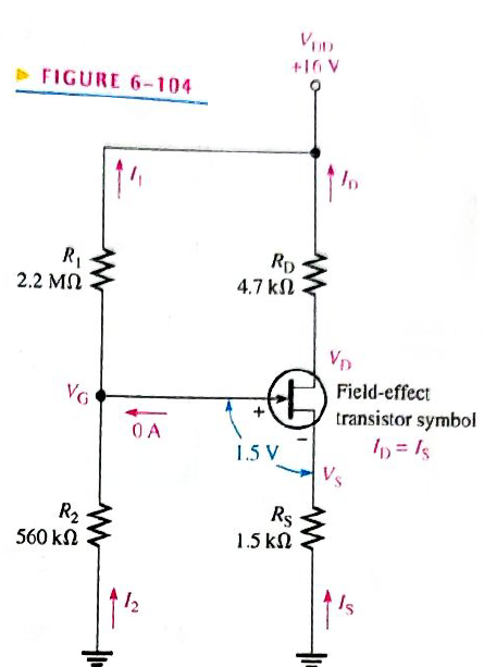
Chapter 6, Problem 58P
Figure 6-104 shows a dc biasing arrangement for a field-effect transistor amplifier. Biasing is a common method for setting up certain dc voltage levels required for proper amplifier operation. Although you may not be familiar with transistor amplifiers at this point, the dc voltages and currents in the circuit can be determined using methods that you already know.
- Find
- with respect to ground
- Determine
- Find
FIGURE 6-104
Expert Solution & Answer
Want to see the full answer?
Check out a sample textbook solution
Students have asked these similar questions
Determine the total input resistance of the emitter-follower in Figure 6-27. Also find
the voltage gain, current gain, and power gain in terms of power delivered to the load,
R. Assume B = 175 and that the capacitive reactances are negligible at the
frequency of operation.
Vee
+10 V
R,
18 KN
2N3904
IV ms
10pF
R.
18 2
10 F
RE
1.0 k2
Voltage Zener is used in the circuit below and the load current is to
vary from 12 to 100 mA. Find the value of series resistance R and the
range of load resistance to maintain a voltage of 7.2 V across the
load. The input voltage is constant at 12V and the minimum Zener
current is 10 mA.
...
IL
R
Iz
Eo
RL
Vz
E, = 12 V
Figure shows a transistor switching circuit. Find the Vcc and Rc, which causes the output voltage
to have a peak to peak value of 6V (given that the input voltage signal Vi, and the output voltage
signal Vo, have units of Volt)
Fone:
V₁
10k2
www
+Vcc
Rc
V₂
B-100
Chapter 6 Solutions
Electronics Fundamentals: Circuits, Devices & Applications
Ch. 6 - Parallel resistors are always connected between...Ch. 6 - If one resistor is connected in series with a...Ch. 6 - In a series-parallel combinational circuit, the...Ch. 6 - A larger load resistor has a smaller loading...Ch. 6 - When measuring de voltage, a DMM will normally...Ch. 6 - When measuring de voltage, the input resistance of...Ch. 6 - When measuring & voltage, the input resistance of...Ch. 6 - A Thevenin circuit consists of a voltage source...Ch. 6 - The internal resistance of an ideal voltage source...Ch. 6 - To transfer maximum power to a load, the load...
Ch. 6 - Which of the following statements are true...Ch. 6 - The total resistance of Figure 6-73 can be found...Ch. 6 - If all of the resistors in Figure 6-73 have the...Ch. 6 - Prob. 4STCh. 6 - The parallel combination of a 330 resistor and a...Ch. 6 - In the circuit described in Question 5, the...Ch. 6 - Prob. 7STCh. 6 - The output of a certain voltage divider is 9V with...Ch. 6 - Prob. 9STCh. 6 - When a load resistance is connected to the output...Ch. 6 - The output voltage of a balanced Wheatstone bridge...Ch. 6 - Prob. 12STCh. 6 - In a certain two-source circuit, one source acting...Ch. 6 - Prob. 14STCh. 6 - Prob. 15STCh. 6 - You are measuring the voltage at a given point in...Ch. 6 - Prob. 1TSCCh. 6 - Determine the cause for each set of symtims. Refer...Ch. 6 - Prob. 3TSCCh. 6 - Determine the cause for each set of symptoms....Ch. 6 - Prob. 5TSCCh. 6 - Identify the series and parallel relationships in...Ch. 6 - Visualize and draw the following series-parallel...Ch. 6 - Visualize and draw the following series-parallel...Ch. 6 - In each circuit of Figure 6-76 identify the series...Ch. 6 - A certain circuit is composed of two parallel...Ch. 6 - For the circuit in Figure 6-77, determine the...Ch. 6 - Determine the total resistance for each circuit in...Ch. 6 - Determine the current through each resistor in...Ch. 6 - Determine the current through each resistor in...Ch. 6 - In Figure 6-78, find the following: total...Ch. 6 - In Figure 6-78, determine the current through R2...Ch. 6 - In Figure 6-78, determine the current through R4...Ch. 6 - A vlotage divider consists of two 56k resistors...Ch. 6 - A 12 V battery output is divided down to obtain...Ch. 6 - Which will cause a smaller decrease in output...Ch. 6 - In Figure 6-79, determine the current drain on the...Ch. 6 - Across which one of the following resistances will...Ch. 6 - A certain voltage divider consists of three 1.0M...Ch. 6 - What is the difference between the measured and...Ch. 6 - By what percentage does the voltmeter in Problem...Ch. 6 - A 10,000/VVOM is used on the 10 V scale to measure...Ch. 6 - If a DMM with 10M input resistance is used instead...Ch. 6 - A resistor of unknown value is connected to a...Ch. 6 - A bridge network is shown In Figure 6-80. To what...Ch. 6 - Determine the value of RX in the balance bridge in...Ch. 6 - Determine the outpur voltage of the unbalanced...Ch. 6 - Reduce the circuit in Figure 6-83 to its Thevenin...Ch. 6 - For each circuit in Figure 6-84, determine the...Ch. 6 - Determine the voltage and current for R1 in Figure...Ch. 6 - Determin the value of a load resistor connected...Ch. 6 - A certain Thevenin equivalent circuit has a...Ch. 6 - Determine the value of RL in Figure 6-84(a) for...Ch. 6 - In Figure 6-86, use ther superposition therorem to...Ch. 6 - In Figure 6-86, What is the curent through R2?...Ch. 6 - Is the voltmeter reading in Figure 6-87 correct?...Ch. 6 - If R2 in Figure 6-88 opens, what voltages will be...Ch. 6 - Check the meter readings in Figure 6-89 and locate...Ch. 6 - Determine the voltage you would expect to measure...Ch. 6 - Determine the voltage you would expect to measure...Ch. 6 - In each circuit of Figure 6-90, identify the...Ch. 6 - Draw the schematic of the PC board layout in...Ch. 6 - 1For the circuit shown in Figure 6-92, calculate...Ch. 6 - Determine the total resistance and the voltage at...Ch. 6 - Determine the total resistance between terminals A...Ch. 6 - What is the voltage across each resistor in Figure...Ch. 6 - Determine the voltage, VAB. in Figure 6-95. FIGURE...Ch. 6 - Find the value of R2 in Figure 6-96. FIGURE 6-96Ch. 6 - Determine the total resistance and the voltage at...Ch. 6 - Develop a voltage divider to provide a 6 V output...Ch. 6 - Determine the resistance values for a voltage...Ch. 6 - Using the superposition therorem, calculate the...Ch. 6 - Find the current through RL in Figure 6-99. FIGURE...Ch. 6 - Using Thevenin’s theorem, find the voltage...Ch. 6 - Determine VOUT for the circuit in Figure 6-101 for...Ch. 6 - Develop a schematic for the double-sided PC board...Ch. 6 - Lay out a PC board for the circuit in Figure...Ch. 6 - The voltage divider in Figure 6-103 has a switched...Ch. 6 - Figure 6-104 shows a dc biasing arrangement for a...Ch. 6 - Look at the voltmeters in Figure 6-105 and...Ch. 6 - Are the voltmeter reading in Figure 6-106 correct?...Ch. 6 - There is one fault in Figure 6-107. Bases on the...Ch. 6 - Look at the voltmeters in Figure 6-108 and...Ch. 6 - Determine the voltmeter reading in Figure 6-108 if...Ch. 6 - Open file P06-64; files are found at...Ch. 6 - www.prenhall.com/floyd. 65. Open file P06-65 and...Ch. 6 - www.prenhall.com/floyd. 66. Open file P06-66 and...Ch. 6 - www.prenhall.com/floyd. 67. Open file P06-67 and...Ch. 6 - www.prenhall.com/floyd. 68. Open file P06-68 and...Ch. 6 - www.prenhall.com/floyd. 69. Open file P06-69 and...Ch. 6 - www.prenhall.com/floyd. 70. Open file P06-70 and...Ch. 6 - www.prenhall.com/floyd. 71. Open file P06-71 and...
Knowledge Booster


Learn more about
Need a deep-dive on the concept behind this application? Look no further. Learn more about this topic, electrical-engineering and related others by exploring similar questions and additional content below.Similar questions
- Example 6-8 For the amplifier in Figure 6-20, (a) Determine the dc collector voltage. (b) Determine the ac collector voltage. (c) Draw the total collector voltage waveform and the total output voltage waveform. Vcc +10 V BDc = 150 Bar = 175 Re 4.7 kN R 47 kf2 eet 10 uF 10 µF 47 kN R. 600 2 10 kN 470 2 10 mv RE2 470 N 100 µFarrow_forwardEmploying the characteristic curve in Figure 1 and obtain the design for a voltage divider configuration that has a Q point of ICQ = 5 mA and VCEQ = 8 V. Using VCC = 24 V and RC = 3RE. Find the following: *Just solve d), e) and f).* a) Draw the configuration indicating each of the elements b) Determine RC and RE c) Find VE d) Determine VB e) Calculate β for point Q f) Find R2 if R1 = 24 kΩarrow_forwardI need to design a power supply 110v , with an output between 6 and 9v. I did a design and I implemented a resistor after the bridge as a surge protector for the diode. I need to know if this is the right design and I need some calculations for the elements to provide an output between 6 and 9v.arrow_forward
- The output current equation to voltage to current convertor circuit is Oi_l=v_in/R Oi_l=v_out/R Oi_l=R/v_in O Elsearrow_forwardEmploying the characteristic curve in Figure 1 and obtain the design for a voltage divider configuration that has a Q point of ICQ = 5 mA and VCEQ = 8 V. Using VCC = 24 V and RC = 3RE. Find the following: a) Draw the configuration indicating each of the elements b) Determine RC and RE c) Find VE d) Determine VB e) Calculate ? for point Q f) Find R2 if R1 = 24 kΩarrow_forwardCircuits: What is the output voltage gain of this circuit? When I run it on CircuitLab I get a voltage gain of 1. But when I calculated it was supposed to be 2. What could be the reason? Image is below and has been uploaded:arrow_forward
- Electrical Engineering How do I create a circuit that does the following. The output voltage Vout is at OV originally. If the input voltage Vin changes from OV to 1V, the Vout should also goes to 1V an will keep as 1V no matter how Vin changes later on. plz help draw the circuit diagram!arrow_forward2.0 a. TMP35 b. TMP36 c. TMP37 +Vs - 3V Using the appropriate curve, develop a linear equation for the output temperature as a function of voltage. 1.8 1.6 E 1.4 1.2 1.0 0.8 0.6 0.4 0.2 -50 -25 25 50 75 100 125 TEMPERATURE (*C) Figure 6. Output Voltage vs. Temperature OUTPUT VOLTAGE (V) 200-20C 00arrow_forwardTwo perfectly matched silicon transistors are connected as shown in figure. The value of the current I is B-1000 1kg + 0.7V -5V +3V B=1000arrow_forward
- What should be the value of the input voltage V1 to have a current of 200uA across R6? Based on this circuitarrow_forwardDetermine the regulated output voltage of the circuit in Figure D IN4O02 Vour LM317 R 2402 D2 ADI IN4002 120 V ms 470uF 1.8 kQ 000arrow_forwardIn the Zener circuit shown below, calculate the Zener current IZ when VZ=10 V, E=14 V, R1=298 ohm, and R2 =298 ohm.arrow_forward
arrow_back_ios
SEE MORE QUESTIONS
arrow_forward_ios
Recommended textbooks for you
 Introductory Circuit Analysis (13th Edition)Electrical EngineeringISBN:9780133923605Author:Robert L. BoylestadPublisher:PEARSON
 Delmar's Standard Textbook Of ElectricityElectrical EngineeringISBN:9781337900348Author:Stephen L. HermanPublisher:Cengage Learning
 Programmable Logic ControllersElectrical EngineeringISBN:9780073373843Author:Frank D. PetruzellaPublisher:McGraw-Hill Education
 Fundamentals of Electric CircuitsElectrical EngineeringISBN:9780078028229Author:Charles K Alexander, Matthew SadikuPublisher:McGraw-Hill Education
 Electric Circuits. (11th Edition)Electrical EngineeringISBN:9780134746968Author:James W. Nilsson, Susan RiedelPublisher:PEARSON
 Engineering ElectromagneticsElectrical EngineeringISBN:9780078028151Author:Hayt, William H. (william Hart), Jr, BUCK, John A.Publisher:Mcgraw-hill Education,
Introductory Circuit Analysis (13th Edition)
Electrical Engineering
ISBN:9780133923605
Author:Robert L. Boylestad
Publisher:PEARSON
Delmar's Standard Textbook Of Electricity
Electrical Engineering
ISBN:9781337900348
Author:Stephen L. Herman
Publisher:Cengage Learning
Programmable Logic Controllers
Electrical Engineering
ISBN:9780073373843
Author:Frank D. Petruzella
Publisher:McGraw-Hill Education
Fundamentals of Electric Circuits
Electrical Engineering
ISBN:9780078028229
Author:Charles K Alexander, Matthew Sadiku
Publisher:McGraw-Hill Education
Electric Circuits. (11th Edition)
Electrical Engineering
ISBN:9780134746968
Author:James W. Nilsson, Susan Riedel
Publisher:PEARSON
Engineering Electromagnetics
Electrical Engineering
ISBN:9780078028151
Author:Hayt, William H. (william Hart), Jr, BUCK, John A.
Publisher:Mcgraw-hill Education,
Current Divider Rule; Author: Neso Academy;https://www.youtube.com/watch?v=hRU1mKWUehY;License: Standard YouTube License, CC-BY