
Electronics Fundamentals: Circuits, Devices & Applications
8th Edition
ISBN: 9780135072950
Author: Thomas L. Floyd, David Buchla
Publisher: Prentice Hall
expand_more
expand_more
format_list_bulleted
Videos
Textbook Question
Chapter 6, Problem 27P
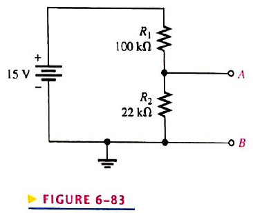
Reduce the circuit in Figure 6-83 to its Thevenin equivalent as viewed from terminals A and B.
FIGURE 6-83
Expert Solution & Answer
Want to see the full answer?
Check out a sample textbook solution
Students have asked these similar questions
Reduce the circuit in Figure 6-82 to its Thevenin equivalent as viewed from terminals A and B.
15 V
FIGURE 6-82
R₁
100 ΚΩ
R₂
22 ΚΩ
OB
the source current through R1 is 6.34 mA. use current divider to determine how much current goes through R5 and R6
4. For the parallel adder in Figure 6-69, determine the complete sum by analysis of the logical
operation of the circuit. Verify your result by longhand addition of the two input numbers.
FIGURE 6-69
10
10
ABC
ABC
А В СМ
C
out
Σ
out
3
Σ
out
5
Σ
Chapter 6 Solutions
Electronics Fundamentals: Circuits, Devices & Applications
Ch. 6 - Parallel resistors are always connected between...Ch. 6 - If one resistor is connected in series with a...Ch. 6 - In a series-parallel combinational circuit, the...Ch. 6 - A larger load resistor has a smaller loading...Ch. 6 - When measuring de voltage, a DMM will normally...Ch. 6 - When measuring de voltage, the input resistance of...Ch. 6 - When measuring & voltage, the input resistance of...Ch. 6 - A Thevenin circuit consists of a voltage source...Ch. 6 - The internal resistance of an ideal voltage source...Ch. 6 - To transfer maximum power to a load, the load...
Ch. 6 - Which of the following statements are true...Ch. 6 - The total resistance of Figure 6-73 can be found...Ch. 6 - If all of the resistors in Figure 6-73 have the...Ch. 6 - Prob. 4STCh. 6 - The parallel combination of a 330 resistor and a...Ch. 6 - In the circuit described in Question 5, the...Ch. 6 - Prob. 7STCh. 6 - The output of a certain voltage divider is 9V with...Ch. 6 - Prob. 9STCh. 6 - When a load resistance is connected to the output...Ch. 6 - The output voltage of a balanced Wheatstone bridge...Ch. 6 - Prob. 12STCh. 6 - In a certain two-source circuit, one source acting...Ch. 6 - Prob. 14STCh. 6 - Prob. 15STCh. 6 - You are measuring the voltage at a given point in...Ch. 6 - Prob. 1TSCCh. 6 - Determine the cause for each set of symtims. Refer...Ch. 6 - Prob. 3TSCCh. 6 - Determine the cause for each set of symptoms....Ch. 6 - Prob. 5TSCCh. 6 - Identify the series and parallel relationships in...Ch. 6 - Visualize and draw the following series-parallel...Ch. 6 - Visualize and draw the following series-parallel...Ch. 6 - In each circuit of Figure 6-76 identify the series...Ch. 6 - A certain circuit is composed of two parallel...Ch. 6 - For the circuit in Figure 6-77, determine the...Ch. 6 - Determine the total resistance for each circuit in...Ch. 6 - Determine the current through each resistor in...Ch. 6 - Determine the current through each resistor in...Ch. 6 - In Figure 6-78, find the following: total...Ch. 6 - In Figure 6-78, determine the current through R2...Ch. 6 - In Figure 6-78, determine the current through R4...Ch. 6 - A vlotage divider consists of two 56k resistors...Ch. 6 - A 12 V battery output is divided down to obtain...Ch. 6 - Which will cause a smaller decrease in output...Ch. 6 - In Figure 6-79, determine the current drain on the...Ch. 6 - Across which one of the following resistances will...Ch. 6 - A certain voltage divider consists of three 1.0M...Ch. 6 - What is the difference between the measured and...Ch. 6 - By what percentage does the voltmeter in Problem...Ch. 6 - A 10,000/VVOM is used on the 10 V scale to measure...Ch. 6 - If a DMM with 10M input resistance is used instead...Ch. 6 - A resistor of unknown value is connected to a...Ch. 6 - A bridge network is shown In Figure 6-80. To what...Ch. 6 - Determine the value of RX in the balance bridge in...Ch. 6 - Determine the outpur voltage of the unbalanced...Ch. 6 - Reduce the circuit in Figure 6-83 to its Thevenin...Ch. 6 - For each circuit in Figure 6-84, determine the...Ch. 6 - Determine the voltage and current for R1 in Figure...Ch. 6 - Determin the value of a load resistor connected...Ch. 6 - A certain Thevenin equivalent circuit has a...Ch. 6 - Determine the value of RL in Figure 6-84(a) for...Ch. 6 - In Figure 6-86, use ther superposition therorem to...Ch. 6 - In Figure 6-86, What is the curent through R2?...Ch. 6 - Is the voltmeter reading in Figure 6-87 correct?...Ch. 6 - If R2 in Figure 6-88 opens, what voltages will be...Ch. 6 - Check the meter readings in Figure 6-89 and locate...Ch. 6 - Determine the voltage you would expect to measure...Ch. 6 - Determine the voltage you would expect to measure...Ch. 6 - In each circuit of Figure 6-90, identify the...Ch. 6 - Draw the schematic of the PC board layout in...Ch. 6 - 1For the circuit shown in Figure 6-92, calculate...Ch. 6 - Determine the total resistance and the voltage at...Ch. 6 - Determine the total resistance between terminals A...Ch. 6 - What is the voltage across each resistor in Figure...Ch. 6 - Determine the voltage, VAB. in Figure 6-95. FIGURE...Ch. 6 - Find the value of R2 in Figure 6-96. FIGURE 6-96Ch. 6 - Determine the total resistance and the voltage at...Ch. 6 - Develop a voltage divider to provide a 6 V output...Ch. 6 - Determine the resistance values for a voltage...Ch. 6 - Using the superposition therorem, calculate the...Ch. 6 - Find the current through RL in Figure 6-99. FIGURE...Ch. 6 - Using Thevenin’s theorem, find the voltage...Ch. 6 - Determine VOUT for the circuit in Figure 6-101 for...Ch. 6 - Develop a schematic for the double-sided PC board...Ch. 6 - Lay out a PC board for the circuit in Figure...Ch. 6 - The voltage divider in Figure 6-103 has a switched...Ch. 6 - Figure 6-104 shows a dc biasing arrangement for a...Ch. 6 - Look at the voltmeters in Figure 6-105 and...Ch. 6 - Are the voltmeter reading in Figure 6-106 correct?...Ch. 6 - There is one fault in Figure 6-107. Bases on the...Ch. 6 - Look at the voltmeters in Figure 6-108 and...Ch. 6 - Determine the voltmeter reading in Figure 6-108 if...Ch. 6 - Open file P06-64; files are found at...Ch. 6 - www.prenhall.com/floyd. 65. Open file P06-65 and...Ch. 6 - www.prenhall.com/floyd. 66. Open file P06-66 and...Ch. 6 - www.prenhall.com/floyd. 67. Open file P06-67 and...Ch. 6 - www.prenhall.com/floyd. 68. Open file P06-68 and...Ch. 6 - www.prenhall.com/floyd. 69. Open file P06-69 and...Ch. 6 - www.prenhall.com/floyd. 70. Open file P06-70 and...Ch. 6 - www.prenhall.com/floyd. 71. Open file P06-71 and...
Knowledge Booster


Learn more about
Need a deep-dive on the concept behind this application? Look no further. Learn more about this topic, electrical-engineering and related others by exploring similar questions and additional content below.Similar questions
- 28. For each circuit in Figure 6-83, determine the Thevenin equivalent as seen from terminals A and B. 2.5 V (a) R₁ 100 (2 R3 www 47 Ω FIGURE 6-83 R₁ 22 (2 R₂ 78 Ω A B R₁ (b) R₁ 100 (2 R₁ B 3 V HOF ✓ R₂ 270 Ω =1.5 V (c) R₁ 100 ΚΩ R₂ 56 ΚΩ B RLarrow_forwardIn Figure 6-85 , use the superposition theorem to find the current in R3 and what is the current through R2 ?arrow_forwardFigure 6-20 R, = 150 2 V = 18 V R= 300 N R= 600 n B R= 100 0arrow_forward
- 28. For the multiplexer in Figure 6-79, determine the output for the following input states: D₁ = 0, D₁ = 1, D₂ = 1, D3 = 0, S₁ = 1, S₁ = 0. So S₁ Do D₁ D₂ D3 MUX } of G 0 1 2 3 Figure 6-79 Yarrow_forward1. Four 0.5 A current sources are connected in parallel in the same direction. What current will be produced through a load resistor? 2. How many 100 mA current sources must be connected in parallel to produce a total current output of 300 mA? Draw a schematic showing the sources connected. 3. In a certain transistor amplifier circuit, the transistor can be represented by a 10 mA current source, as shown in Figure 6-31. In a certain transistor amplifier, two transis- tors act in parallel. How much current is there through the resistor Re? » FIGURE 6-31 D10 mA D10 mA RE 1.0 karrow_forward4. For the parallel adder in Figure 6-69, determine the complete sum by analysis of the logical operation of the circuit. Verify your result by longhand addition of the two input numbers. Figure 6-69 Figure 6-70 1 0 A B Cin Cout Σε Σ A B Cin Σε Cout ΣΑ Σ 5. Repeat Problem 4 for the circuit and input conditions in Figure 6-70. Ο Ο A B Cin Cout Σ 1 0 ΣΑ A B Cin| Cout Σ A B Cin Cout Σ A B C Σ; Cout Σ 0 1 Σ A B Cin Cout Σ Στ A B Cin Cout Σarrow_forward
- 6. When using superposition, what is the ideal internal resistance of a current source? Short circuit The source voltage divided by the source resistance The source voltage divided by the load resistance Infinite resistancearrow_forwardCalculate the equivalent resistance R ab across the terminals a-b without using PSPICE for circuit in the given Figurearrow_forwardMost schematic diagrams are made up of _____. a. series circuits b. parallel circuits c. series-parallel circuits d. none of the abovearrow_forward
- Parallel circuits are used in the air-conditioning industry to __________. a. supply the correct line voltage to several circuits b. act as a safety circuit c. divide the voltage between two major loads d. all of the abovearrow_forwardReduce the circuit to a single current source with a resistor in parallelarrow_forwardFind the Thevenin voltage (vth) and Thevenin resistance (rth) according to the a-b ends of the circuit in the figure 6V 3Ω 10V 40 12 b. 5V 4Aarrow_forward
arrow_back_ios
SEE MORE QUESTIONS
arrow_forward_ios
Recommended textbooks for you
 Electricity for Refrigeration, Heating, and Air C...Mechanical EngineeringISBN:9781337399128Author:Russell E. SmithPublisher:Cengage Learning
Electricity for Refrigeration, Heating, and Air C...
Mechanical Engineering
ISBN:9781337399128
Author:Russell E. Smith
Publisher:Cengage Learning
Lesson 2 - Source Transformations, Part 2 (Engineering Circuits); Author: Math and Science;https://www.youtube.com/watch?v=7gno74RhVGQ;License: Standard Youtube License