
Electronics Fundamentals: Circuits, Devices & Applications
8th Edition
ISBN: 9780135072950
Author: Thomas L. Floyd, David Buchla
Publisher: Prentice Hall
expand_more
expand_more
format_list_bulleted
Concept explainers
Videos
Textbook Question
Chapter 6, Problem 57P
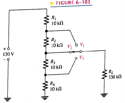
The voltage divider in Figure 6-103 has a switched load. Determine the voltage at each tap
FIGURE 6-103
Expert Solution & Answer
Want to see the full answer?
Check out a sample textbook solution
Students have asked these similar questions
Calculate
RT
for each circuit in Figure 6–66.
Determine the voltage and current for RL in Figure 6-84.
FIGURE 6-84
5 SV
R₁
1.0 ΚΩ
R₂
2.2 ΚΩ
RL B
Μ
4,7 ΚΩ
R₂
1.1 ΚΩ
R₂
1.5 ΚΩ
Determine the value of a load resistor connected between terminals A and B in Figure 6-82 for maximum power transfer to the load resistor.
Chapter 6 Solutions
Electronics Fundamentals: Circuits, Devices & Applications
Ch. 6 - Parallel resistors are always connected between...Ch. 6 - If one resistor is connected in series with a...Ch. 6 - In a series-parallel combinational circuit, the...Ch. 6 - A larger load resistor has a smaller loading...Ch. 6 - When measuring de voltage, a DMM will normally...Ch. 6 - When measuring de voltage, the input resistance of...Ch. 6 - When measuring & voltage, the input resistance of...Ch. 6 - A Thevenin circuit consists of a voltage source...Ch. 6 - The internal resistance of an ideal voltage source...Ch. 6 - To transfer maximum power to a load, the load...
Ch. 6 - Which of the following statements are true...Ch. 6 - The total resistance of Figure 6-73 can be found...Ch. 6 - If all of the resistors in Figure 6-73 have the...Ch. 6 - Prob. 4STCh. 6 - The parallel combination of a 330 resistor and a...Ch. 6 - In the circuit described in Question 5, the...Ch. 6 - Prob. 7STCh. 6 - The output of a certain voltage divider is 9V with...Ch. 6 - Prob. 9STCh. 6 - When a load resistance is connected to the output...Ch. 6 - The output voltage of a balanced Wheatstone bridge...Ch. 6 - Prob. 12STCh. 6 - In a certain two-source circuit, one source acting...Ch. 6 - Prob. 14STCh. 6 - Prob. 15STCh. 6 - You are measuring the voltage at a given point in...Ch. 6 - Prob. 1TSCCh. 6 - Determine the cause for each set of symtims. Refer...Ch. 6 - Prob. 3TSCCh. 6 - Determine the cause for each set of symptoms....Ch. 6 - Prob. 5TSCCh. 6 - Identify the series and parallel relationships in...Ch. 6 - Visualize and draw the following series-parallel...Ch. 6 - Visualize and draw the following series-parallel...Ch. 6 - In each circuit of Figure 6-76 identify the series...Ch. 6 - A certain circuit is composed of two parallel...Ch. 6 - For the circuit in Figure 6-77, determine the...Ch. 6 - Determine the total resistance for each circuit in...Ch. 6 - Determine the current through each resistor in...Ch. 6 - Determine the current through each resistor in...Ch. 6 - In Figure 6-78, find the following: total...Ch. 6 - In Figure 6-78, determine the current through R2...Ch. 6 - In Figure 6-78, determine the current through R4...Ch. 6 - A vlotage divider consists of two 56k resistors...Ch. 6 - A 12 V battery output is divided down to obtain...Ch. 6 - Which will cause a smaller decrease in output...Ch. 6 - In Figure 6-79, determine the current drain on the...Ch. 6 - Across which one of the following resistances will...Ch. 6 - A certain voltage divider consists of three 1.0M...Ch. 6 - What is the difference between the measured and...Ch. 6 - By what percentage does the voltmeter in Problem...Ch. 6 - A 10,000/VVOM is used on the 10 V scale to measure...Ch. 6 - If a DMM with 10M input resistance is used instead...Ch. 6 - A resistor of unknown value is connected to a...Ch. 6 - A bridge network is shown In Figure 6-80. To what...Ch. 6 - Determine the value of RX in the balance bridge in...Ch. 6 - Determine the outpur voltage of the unbalanced...Ch. 6 - Reduce the circuit in Figure 6-83 to its Thevenin...Ch. 6 - For each circuit in Figure 6-84, determine the...Ch. 6 - Determine the voltage and current for R1 in Figure...Ch. 6 - Determin the value of a load resistor connected...Ch. 6 - A certain Thevenin equivalent circuit has a...Ch. 6 - Determine the value of RL in Figure 6-84(a) for...Ch. 6 - In Figure 6-86, use ther superposition therorem to...Ch. 6 - In Figure 6-86, What is the curent through R2?...Ch. 6 - Is the voltmeter reading in Figure 6-87 correct?...Ch. 6 - If R2 in Figure 6-88 opens, what voltages will be...Ch. 6 - Check the meter readings in Figure 6-89 and locate...Ch. 6 - Determine the voltage you would expect to measure...Ch. 6 - Determine the voltage you would expect to measure...Ch. 6 - In each circuit of Figure 6-90, identify the...Ch. 6 - Draw the schematic of the PC board layout in...Ch. 6 - 1For the circuit shown in Figure 6-92, calculate...Ch. 6 - Determine the total resistance and the voltage at...Ch. 6 - Determine the total resistance between terminals A...Ch. 6 - What is the voltage across each resistor in Figure...Ch. 6 - Determine the voltage, VAB. in Figure 6-95. FIGURE...Ch. 6 - Find the value of R2 in Figure 6-96. FIGURE 6-96Ch. 6 - Determine the total resistance and the voltage at...Ch. 6 - Develop a voltage divider to provide a 6 V output...Ch. 6 - Determine the resistance values for a voltage...Ch. 6 - Using the superposition therorem, calculate the...Ch. 6 - Find the current through RL in Figure 6-99. FIGURE...Ch. 6 - Using Thevenin’s theorem, find the voltage...Ch. 6 - Determine VOUT for the circuit in Figure 6-101 for...Ch. 6 - Develop a schematic for the double-sided PC board...Ch. 6 - Lay out a PC board for the circuit in Figure...Ch. 6 - The voltage divider in Figure 6-103 has a switched...Ch. 6 - Figure 6-104 shows a dc biasing arrangement for a...Ch. 6 - Look at the voltmeters in Figure 6-105 and...Ch. 6 - Are the voltmeter reading in Figure 6-106 correct?...Ch. 6 - There is one fault in Figure 6-107. Bases on the...Ch. 6 - Look at the voltmeters in Figure 6-108 and...Ch. 6 - Determine the voltmeter reading in Figure 6-108 if...Ch. 6 - Open file P06-64; files are found at...Ch. 6 - www.prenhall.com/floyd. 65. Open file P06-65 and...Ch. 6 - www.prenhall.com/floyd. 66. Open file P06-66 and...Ch. 6 - www.prenhall.com/floyd. 67. Open file P06-67 and...Ch. 6 - www.prenhall.com/floyd. 68. Open file P06-68 and...Ch. 6 - www.prenhall.com/floyd. 69. Open file P06-69 and...Ch. 6 - www.prenhall.com/floyd. 70. Open file P06-70 and...Ch. 6 - www.prenhall.com/floyd. 71. Open file P06-71 and...
Knowledge Booster


Learn more about
Need a deep-dive on the concept behind this application? Look no further. Learn more about this topic, electrical-engineering and related others by exploring similar questions and additional content below.Similar questions
- 22. A 7-segment decoder/driver drives the display in Figure 6–78. If the waveforms are applied as indicated, determine the sequence of digits that appears on the display. BCD/7-seg Ao A1 Ap A1 A2 b A2 4 d A3 Az 8 FIGURE 6-78arrow_forwardDetermine the value of Rx in the balanced bridge in Figure 6-80.arrow_forward22. A 7-segment decoder/driver drives the display in Figure 6-78. If the waveforms are applied as indicated, determine the sequence of digits that appears on the display. BCD/7-seg Ao a b A1 Ag 2 Az Az 4 8. FIGURE 6-78arrow_forward
- Determine the output voltage of the unbalanced bridge in Figure 6-81 for a temperature of 65°C. The thermistor has a nominal resistance of 1 k2 at 25°C and a positive temperature coef- ficient. Assume that its resistance changes 5 for each C° change in temperature. R₁ Thermistor R3 1.0 ΚΩ +9 V B3 VOO R₂ 1.0 ΚΩ R4 1.0 ΚΩ FIGURE 6-81arrow_forwardTwo 1 k ohm resistors are in series and this series combination is in parallel with a 2.2 k ohm resistor. The voltage across one of the 1 k ohm resistors is 6 V. The voltage across the 2.2 k ohm resistor isarrow_forward4. For the parallel adder in Figure 6-69, determine the complete sum by analysis of the logical operation of the circuit. Verify your result by longhand addition of the two input numbers. FIGURE 6-69 10 10 ABC ABC А В СМ C out Σ out 3 Σ out 5 Σarrow_forward
- A 12 V potential difference is applied across a series combination of four 6 Q resistors. The current in each resistor isarrow_forwardSECTION 5-6 Kirchhoff's Voltage Law 32. The following voltage drops are measured across three resistors in series: 5.5 V, 8.2 V, and 12.3 V. What is the value of the source voltage to which these resistors are connected? 33. Five resistors are in series with a 20 V source. The voltage drops across four of the resistors are 1.5 V, 5.5 V, 3 V, and 6 V. How much voltage is dropped across the fifth resistor? 34. Determine the unspecified voltage drop(s) in each circuit of Figure 5-78. Show how to connect a voltmeter to measure cach unknown voltage drop. ► FIGURE 5-78 2 V V2 3.2 V 8 V R 15 VE 2R 0.5 V 1.5 V 4 R 3R (b)arrow_forwardFigure 6-20 R, = 150 2 V = 18 V R= 300 N R= 600 n B R= 100 0arrow_forward
- Determine the resistance values using the color code and calculate all missing values in Figure 6-27. FIGURE 6-27 Determine resistor values using the color and find all missing electrical values.arrow_forwardA series circuit contains the following values of resistors: R1=510R2=680R3=390R4=750 Assume a source voltage of 48 V. Use the general voltage divider formula to calculate the voltage drop across each of the resistors. E1=VE2=VE3=VE4=Varrow_forwardRefer to the circuit shown in Figure 6-22. The circuit has an applied voltage of 24 V and the resistors have values as follows: R1=1kR2=300R3=750R4=1k An ammeter and a voltmeter indicate the following values: IT=42.5mAI1=24mAE1=24VI2=18.5mAE2=5.5VI3=0AE3=18.5VI4=18.5mAE4=18.5V What is the most likely problem with this circuit? FIGURE 8-22 Determine resistor values using the color code and find all missing electrical values.arrow_forward
arrow_back_ios
SEE MORE QUESTIONS
arrow_forward_ios
Recommended textbooks for you
 Delmar's Standard Textbook Of ElectricityElectrical EngineeringISBN:9781337900348Author:Stephen L. HermanPublisher:Cengage Learning
 Electricity for Refrigeration, Heating, and Air C...Mechanical EngineeringISBN:9781337399128Author:Russell E. SmithPublisher:Cengage Learning
Delmar's Standard Textbook Of Electricity
Electrical Engineering
ISBN:9781337900348
Author:Stephen L. Herman
Publisher:Cengage Learning
Electricity for Refrigeration, Heating, and Air C...
Mechanical Engineering
ISBN:9781337399128
Author:Russell E. Smith
Publisher:Cengage Learning
What is an electric furnace and how does it work?; Author: Fire & Ice Heating and Air Conditioning Inc;https://www.youtube.com/watch?v=wjAWecPGi0M;License: Standard Youtube License