
Concept explainers
Videos
A geometric stress concentration factor, K,, is used to relate the actual maximum stress to a well- defined nominal stress in a structural member. The maximum stress is given by = K,ao, where amaM represents the maximum stress and
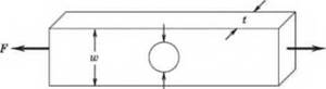

Consider the axial loading shown in Figure 5.9, where the structural member is in axial tension and experiences a stress concentration as a result of a trans-verse hole. In this geometry, o0 = F/A, where area A = (w — d)t. If d = 0.5 w, then K, = 2.2. Suppose F = 10.0(X) ± 500 N, w = 1.5 ± 0.02 cm, t = 0.5 ± 0.02 cm, and the uncertainty in the value for d is 3%. Neglecting the uncertainty in stress concentration Factor, determine the uncertainty in the maximum stress experienced by this part.
Figure 5.9 Structural member discussed in Problem 5.58.
Want to see the full answer?
Check out a sample textbook solution
Chapter 5 Solutions
Theory and Design for Mechanical Measurements


- A circular pipe of internal diameter 30 mm and thickness 4 mm is subjected to a force 30 kN and the elongation was measured as 1 mm. If the length of the pipe is 2 m, find the value of Young's modulus of elasticity and the stress in the pipe. Match each item to a choice: Young's Modulus (GPa) Stress (MPa): Choices: : 140.4 # 47.9 B 56.4 # 120.8 #240.8 8 70.2arrow_forwardThe nodal coordinates and the nodal displacements for some plane stress elastic element is listed in the following problem. The element is 0.1 m thick. The coordinates and displacements are given in meters. (a) Calculate K(1,1) of the element stiffness matrix (b) Calculate the element stress [16 D = 106| 4 4 01 16 0 (N/m²) 61 1 N1 = (a1 + bịx+ Cy) 2A 1 N2 = 2A -(a2 + b2x + c2y) 1 Na = (az + bzx + C3y) 2A b1 = y2 - y3 a1 = X2y3 - X3y2 a2 = X3y1 - X1y3 C1 = X3 – X2 C2 = X1 – X3 C3 = X2 - X1 b2 = y3 - Yı az = X1y2 - X2y1 b3 = y1 - Y2 X1 = 2 X2 = 1 X3 = 1 y2 = 1 v2 = 0.001 Y1 = 2 Y3 = 0 U1 = 0.003 Uz = 0.0015 V1 = 0 v2 = -0.003 v3 = 0.0arrow_forwardCalcuate Bending From Point A to Point B and Point A to Point C, Calcuate torsion From Point A to Point C. Draw a FBD from point A to point B and another for point A to C indicating what stresses are been calculate. Use the stress tensor and stress cube to Indicate what forces are acting at point A. Force apply at point B is 70lb Distacen from Point A to B is 12 in or 1 feet long Distacen from Point A to C is 3 in Handle diameter 0.625 inarrow_forward
- For the figure shown below (not to scale)... (a) Write equations for the internal forces at J (axial (F), shear (V), and bending (M)) in terms of only P and a. (b) Graph your equations as functions of P, using a =45°, from 0arrow_forward(Solid Mechanics) This plate is clamped into a wall is subjected to a force F as shown. The wall does not generate any stress concentration. At the fillets the stress concentration factor is given Kt = 1.5 (No need of using charts). The plate is made of a steel with the following properties:Modulus E=200 GPaYield stress Sy=200 MPaStrain at failure = 20%Where and how could the plate fail and at which force Fmax? (neglecting transverse shear when calculating Fmax)arrow_forwardQ.4. A 30 m tape weighs 12 g/m and has a cross sectional area of 0.020 cm². It measures correctly when supported throughout under a tension of 85 N and at a temperature of 20°C. When used in the field, the tape is only supported at its ends, under a tension of 85 N. The temperature is 13°C. What is the distance of zero and 30 mark under these conditions?arrow_forwardThe state of stress at a point on a thin plate is as shown in the left side of the Figure below. Determine the state of stress (ox, oy, txy) represented on the element oriented as shown on the right. 120 Sigma_x^prime (MPa) 200 Sigma_y^prime (MPa) 60 Tau_xy^prime (MPa) 30 Alpha (degrees) O x' Oy Txy' Txy Oxarrow_forwardthe ability of fluid to resist shear stresses is known as bulk modulus Select one: O True O Falsearrow_forwardstress and strain A steel rod is 0.02 mi n diameter, and 2.5 m in length. The modulus of elasticity of this material is 210 GPa and a Poison's Ratio of 0.2. The change in diameter after applying a tensile force of 150 KN isarrow_forwardLearning Goal: To calculate the shear stress at a point in the web of an l- beam section subjected to a shear force. When a beam section is subjected to a shear load, a shear stress distribution is developed on the section. The distribution of the shear stress is not linear. Elasticity theory can be used to calculate the shear stress at any point. However, a simpler method can be used to calculate the average shear stress across the width of the section, a distance y above or below the neutral axis. The average VQ shear stress is given by T = Here V is the shear It force on the section, I is the moment of inertia of the entire section about the neutral axis, and ₺ is the width of the section at the distance y where the shear stress is being calculated. Q is the product of the area of the section above (or below) y and the distance from the neutral axis to the centroid of that area (Figure 1). In short, Qis the moment of the area about the neutral axis. Figure 1 of 1 An I-beam has a…arrow_forwardYou need the shear modulus for a particular material in order to calculate shear strain for a known applied shear shear stress. You can't find shear modulus for the material, but you can find elastic modulus (200 GPa) and Poisson's ratio (0.3). Which of the following could you use as the shear modulus for your calculations? 200 GPa O 60 GPa O 77 GPa O 154 GPaarrow_forwardMaterial property of the given system: Tensile strengthσt=11000 daN / cm^2 and Torsional strengthSince τ=5000 daN /cm^2, find the System's Coefficient of Safety (EMF cis) for only point A using the MOH'R circle method?(Dimensions are given on the system) Rod diameter D=4 cm, Rod length L=100 cm, Vertical applied to the rodforce F=500 daN and Torque T=1000 daN cmarrow_forwardarrow_back_iosSEE MORE QUESTIONSarrow_forward_ios
 Elements Of ElectromagneticsMechanical EngineeringISBN:9780190698614Author:Sadiku, Matthew N. O.Publisher:Oxford University Press
 Mechanics of Materials (10th Edition)Mechanical EngineeringISBN:9780134319650Author:Russell C. HibbelerPublisher:PEARSON
 Thermodynamics: An Engineering ApproachMechanical EngineeringISBN:9781259822674Author:Yunus A. Cengel Dr., Michael A. BolesPublisher:McGraw-Hill Education
 Control Systems EngineeringMechanical EngineeringISBN:9781118170519Author:Norman S. NisePublisher:WILEY
 Mechanics of Materials (MindTap Course List)Mechanical EngineeringISBN:9781337093347Author:Barry J. Goodno, James M. GerePublisher:Cengage Learning
 Engineering Mechanics: StaticsMechanical EngineeringISBN:9781118807330Author:James L. Meriam, L. G. Kraige, J. N. BoltonPublisher:WILEY