
(a)
To select:
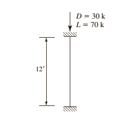
American standard channel for the given compression member using LRFD.
Answer to Problem 4.8.4P
Explanation of Solution
Given information:
Given compression member is :

Calculation:
Calculate the factored load by LRFD by using the equation.
Here
Substitute
Try a C section
AISC must be used, as this shape is non slender and is neither a double angle nor a tee shape
Check the effective slenderness ratio about y-axis using the formula.
Here K is the effective length factor
L is the length of the member between the supports.
r is the radius of gyration
Take the properties steel from the AISC steel table. K value depends on the end conditions
Calculate the elastic buckling stress using the formula.
Check for slenderness ratio by using the formula.
Here
Substitute
Since
Calculate the nominal compressive strength of column using the formula.
Substitute,
=
=
Calculate design strength of the column using by LRFD method
Here we have
Check the effective slenderness ratio about x-axis using the formula.
Substitute
From the manual companion CD:
Calculate the elastic buckling stress using the formula.
Calculate the value of
Calculate the total stress by equation
Calculate the value of
In order to determine which compressive strength equation to be use, compare the value of
Since
Calculate the maximum strength by using the formula.
.
Conclusion:
(b)
To select:
American standard channel for the given compression member using ASD.
Answer to Problem 4.8.4P
Explanation of Solution
Given information:
Given compression member is
Calculation:
Calculate the factored load by LRFD by using the equation.
He re
Substitute
Try a C section
AISC must be used, as this shape is non slender and is neither a double angle nor a tee shape
Check the effective slenderness ratio about y-axis using the formula
Here K is the effective length factor
L is the length of the member between the supports
r is the radius of gyration
Take the properties steel from the AISC steel table. K value depends on the end conditions
Calculate the elastic buckling stress using the formula.
Check for slenderness ratio by using the formula.
Here
Substitute
Since
Calculate the nominal compressive strength of column using the formula.
Substitute,
=
=
Calculate design strength of the column using by ASD method.
Here we have
Check the effective slenderness ratio about x-axis using the formula.
Substitute
From the manual companion CD:
Calculate the elastic buckling stress using the formula.
Calculate the value of
Calculate the total stress by equation
Calculate the value of
In order to determine which compressive strength equation to be use, compare the value of
Since
Calculate the maximum strength by using the formula.
Conclusion:
Want to see more full solutions like this?
Chapter 4 Solutions
Steel Design (Activate Learning with these NEW titles from Engineering!)

- A gravity retaining wall is shown in the figure below. Calculate the factor of safety with respect to overturning and sliding, given the following data: Wall dimensions: H = 6 m, x1 = 0.6 m, x2 = 2 m, x3 = 2m, x4 0.5 m, x5 = 0.75 m, x6 = 0.8 m, D= 1.5 m Soil properties: 71 = 15.5 kN/m³, ₁ = 32°, Y2 = 18 kN/m³, 2=22°, c₂ = 40 kN/m² H x6 X2 TXT X3 Use Coulomb's active earth pressure in your calculation and let ' = 2/3 01. Use Yconcrete = 23.58 kN/m³. Also, use k₁ = k₂ = 2/3 and P = 0 in equation FS (sliding) (ΣV) tan(k₁₂2) + Bk2c + Pp Pa cos a For 1 = 32°, a = 0°, B = 71.57°, Ka = 0.45, 8' = 21.33°. (Enter your answers to three significant figures.) FS (overturning) FS (sliding) =arrow_forwardFor the cantilever retaining wall shown in the figure below, let the following data be given: Wall dimensions: H = 6.5 m, x1 = 0.3 m, x2 = 0.6 m, x3 = 0.8 m, x4 2 m, x5 = 0.8 m, D= 1.5 m, a = 0° Soil properties: 71 = 17.08 kN/m³, ₁ = 36°, Y2 = 19.65 kN/m³, 2 = 15°, c₂ = 30 kN/m² For 2=15°: N = 10.98; N₁ = 3.94; N₁ = 2.65. x2 .. c₁ = 0 Φί H x5 Calculate the factor of safety with respect to overturning, sliding, and bearing capacity. Use Yconcrete = 24.58 kN/m³. Also, use k₁ = k2 = 2/3 and P₂ = 0 in equation (EV) tan(k102) + Bk2c₂ + Pp FS (sliding) Pa cos a (Enter your answers to three significant figures.) FS (overturning) FS (sliding) FS (bearing) = = =arrow_forwardA) # of Disinfection Clearwells: 3 B) Clearwell Operation Style: Parallel (to provide contact time for disinfection using free chlorine (derived from a hypochlorite solution generated onsite). C) The facility's existing system to generate hypochlorite onsite has reached the end of its useful life, and the current operating capacity is insufficient to generate the required mass flow of hypochlorite to accommodate the future capacity of 34.5 MGD. Assume the facility plans to stop generating hypochlorite onsite and will instead purchase a bulk solution of sodium hypochlorite D) Sodium hypochlorite (NaOCI) concentration: 6.25% NaOCI by mass E) Bulk Density: 1,100 kg/m^3 F) Clearwell T10/DT Ratio: (CW1 0.43). (CW2 = 0.51), (CW3 = 0.58) DT is the theoretical mean hydraulic retention time (V/Q) G) pH: 7.0 H) Design Temperature: 15°C 1) 50% of Chlorine is lost in each clearwell J) If the concentration going into the clearwell is C, then you can assume that the concentration leaving the…arrow_forward
- Please explain step by step, and show formulaarrow_forwardNote: Please deliver a clear, step-by-step simplified handwritten solution (without any explanations) that is entirely manually produced without AI assistance. I expect an expert-level answer, and I will evaluate and rate it based on the quality and accuracy of the work, using the provided image for additional reference. Ensure every detail is thoroughly checked for correctness before submission.arrow_forwardPlease don't explain it. But draw it out for me kindly. And appreciate your time!. All the info is in the images. Thanks!.arrow_forward
- Design a simply supported one-way pavement slab for a factored applied moment, Mu = 10 ft-kip. Use f c’ = 5,000 psi and f y = 60,000 psi. The slab is in permanent contact with soil.Hint:• Estimate a minimum slab thickness for deflection control.• Solve for the slab steel based on cover for soil contactarrow_forwardThe figures below shows the framing plan and section of a reinforced concrete floor system. Floor beams are shown as dotted lines. The weight of the ceiling and floor finishing is 6 psf, that of the mechanical and electrical systems is 7 psf, and the weight of the partitions is 180 psf. The floor live load is 105 psf. The 7 in. thick slab exterior bay (S-1) is reinforced with #5 rebars @ 10 in. o.c. as the main positive reinforcement at the mid span, and #4 @ 109 in. for the shrinkage and temperature reinforcement. The panel is simply supported on the exterior edge and monolithic with the beam at the interior edge. Check the adequacy of the slab. Use the ACI moment coefficients. fc’ = 6,000 psi and fy = 60,000 psi. The slab is in an interior location. Hint: • Estimate total dead load. Find factored maximum positive bending moment in the end span. • Find design positive moment capacity. • Compare and determine adequacy, including safety and economy.arrow_forward1 For an reinforced concrete two-way slab shown in figure under the load (P). (the slab continuous over all edges - all sides are fixed), Determine (By using yield line theory): A- Draw the Yield line Pattern B- Determine the moment m C- Find The required flexural steel to resist the loads causing the slab to collapse if P = 200 KN, f=28 MPa, fy = 420 MPa d = 120 mm. Use 10 mm bars. (Prin = 0.002) +2 m 6 m -8 m 3 marrow_forward
- At a point on the surface of a generator shaft the stresses are σx = -55MPa, σy = 25MPa and Txy = -20MPa as shown in Figure Q1. (a) Using either analytical method or Mohr's circle determine the following: Stresses acting on an element inclined at an angle 0 = 35°, i. ii. iii. The maximum shear stress The principal stresses and B. 25 MPa A 55 MPa 20 MPa Figure 1:Material stress state (b) Consider that the Young's modulus for the material, E = 200kPa and Poisson's ratio, v = 0.25. i. ii. determine associate strains for the material with the stress as shown in Figure 1 determine associate strains for the material with the stress at element oriented at 35° (question 1a(i))arrow_forwardA study reports data on the effects of the drug tamoxifen on change in the level of cortisol-binding globulin (CBG) of patients during treatment. With age = x and ACBG = y, summary values are n = 26, Σx, = 1612, Σ(x, - x)² = 3756.96, Σy, = 281.9, Σ(y, - y)² = 465.34, and Ex,y,= 16,745. (a) Compute a 90% CI for the true correlation coefficient p. (Round your answers to four decimal places.) (b) Test Hop=-0.5 versus H: p< -0.5 at level 0.05. Calculate the test statistic and determine the P-value. (Round your test statistic to two decimal places and your P-value to four decimal places.) z = P-value = State the conclusion in the problem context. ◇ Reject Ho. There is no evidence that p < -0.5. ○ Fail to reject Ho. There is evidence that p < -0.5. Reject Ho. There is evidence that p < -0.5. Fail to reject Ho. There is no evidence that p < -0.5. (c) In a regression analysis of y on x, what proportion of variation in change of cortisol-binding globulin level could be explained by variation in…arrow_forwardFor the frame and loading shown, determine the reactions at A and C. 24 Last 2 student ID+50 lbs 24 A 3 in. B A=Last 2 student ID+10 Inch B=Last 2 student ID+40 Inch A B Darrow_forward
 Steel Design (Activate Learning with these NEW ti...Civil EngineeringISBN:9781337094740Author:Segui, William T.Publisher:Cengage Learning