
Concept explainers
Videos
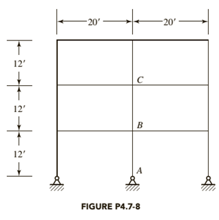
The frame shown in Figure P4.7-8 is unbraced, and bending is about the x-axis of the members. All beams are
a. Determine the effective length factor
b. Determine the effective length factor
c. If

Trending nowThis is a popular solution!

Chapter 4 Solutions
Steel Design (Activate Learning with these NEW titles from Engineering!)


- Studies have shown that the traffic flow on a two-lane road adjacent to a school can be described by the Greenshields model. A length of 0.5 mi adjacent to a school is described as a school zone (see the figure) and operates for a period of 30 min just before the start of school and just after the close of school. The posted speed limit for the school zone during its operation is 15 mi/h. Data collected at the site when the school zone is not in operation show that the jam density and mean free speed for each lane are 136 veh/mi and 63 mi/h. If the demand flow on the highway at the times of operation of the school zone is 90% of the capacity of the highway, determine the following. 0.5 mile School Zone (a) the velocity of the shock wave created by the operation of the school zone (Enter the velocity of the backward forming shock wave in mi/h. Indicate the direction with the sign of your answer.) mi/h (b) the number of vehicles affected by the school zone during this 30-minute operation…arrow_forwardI will rate, thanks!arrow_forwardneed help.arrow_forward
- i want to find books or articles about English romanticism and eclecticism and Robert Smith architect and i need to have the references alsoarrow_forwardBriefly describe which is more important, a resume or a cover letter?Why? What is the purpose of the resume? What is the purpose of thecover letter?arrow_forwardA cylindrical container of internal diameter and height H =200 mm is filled with concrete asshown in the figure below. Beginning at room temperature (T = 20oC), the temperature isdecreased until the concrete develops internal tensile stress that may results in crack (as shown inthe figure on the right below). This is due to the thermal shrinkage of the concrete and strongadhesion between the concrete and the walls of the container. D = 100 mmDetermine the temperature at which the concrete develops a tensile crack.Hint: Assume that the concrete remains linearly elastic until failure.Information about concrete:E = 30 GPa (Young’s Modulus)ν = 0.2 (Poisson’s Ratio)α = 12 ·10-6mm/mm/ oC (Coefficient of thermal expansion)(σt)max = 3 MPa (tensile strength)arrow_forward
- I will rate, thanks!arrow_forward1- Present worth analysis An Environmental engineer is considering two materials for use in a sustainable building. All estimates are made below. (a) Which should be selected on the basis of a present worth comparison at an interest rate of 12% per year? (b) At what first cost for the material not selected above will it become the more economical alternative? يفكر مهندس بيئة في الاختيار بين مادتين لاستخدامهما في انشاء مبنى مستدام كافة البيانات الاقتصادية الخاصة بالمادتين مذكورة في الجدول ادناه. (أ) أي المادتين ستختار على أساس مقارنة القيمة الحالية ) present worth analysis) اذا كان معدل الفائدة 12% سنويًا؟ (ب) كم يجب ان تصبح الكلفة الاولية رأس المال) للمادة غير المختارة أعلاه لتصبح البديل الافضل اقتصاديا؟ Material A First Cost 15000 Maintenance cost 9000 Salvage value 2000 Life 5 Material B 35000 7000 20000 5 2- IRR analysis A manufacturer of hydraulic equipment is trying to determine whether it should use monoflange double block and bleed (DBB) valves or a multi-valve system (MVS) for…arrow_forwardModels of Traffic Flow (Section 5.4) 5.7 An observer has determined that the time headways between successive vehicles on a section of highway are exponentially distributed and that 65% of the headways between vehicles are 9 seconds or greater. If the observer decides to count traffic in 30- second time intervals, estimate the probability of the observer counting exactly four vehicles in an interval. 5.8 At a specified point on a highway vehicles arearrow_forward
- 7.2 An intersection has a four-timing-stage signal with the movements allowed in each timing stage and corresponding analysis and saturation flow rates shown in Table 7.7. Calculate the sum of the flow ratios for the critical lane groups.arrow_forward5.27 At a parking lot, vehicles arrive according to a Poisson process and are processed (parking fee collected) at a uniform deterministic rate at a single station. The mean arrival rate is 4.2 veh/min and the processing rate is 5 veh/min. Determine the average length of queue, the average time spent in the system, and the average waiting time in the queue. 5.28 Consider the parking lot and conditions described in Problem 5.27. If the rate at which vehicles are processed became exponentially distributed (instead of deterministic) with a mean processing rate of 5 veh/min, what would be the average length of queue, the average time spent in the system, and the average waiting time in the queue?arrow_forwardDetermine the heel and toe stresses and the factor of safeties for sliding and overturning for the gravity dam section shown in the figure below for the following loading conditions: - Horizontal earthquake (Kh) = 0.1 - Normal uplift pressure with gallery drain working - Silt deposit up to 30 m height - No wave pressure and no ice pressure -Unit weight of concrete = 2.4 Ton/m³ and unit weight of silty water = 1.4 Ton/m³ - Submerged weight of silt = 0.9 Ton/m³ - Coefficient of friction = 0.65 and angle of repose = 25° Solve this question with the presence of gallery and without gallery., discuss the issue in both cases.... 144 m E 4m W 8m 6m 8m7m 120marrow_forward
 Steel Design (Activate Learning with these NEW ti...Civil EngineeringISBN:9781337094740Author:Segui, William T.Publisher:Cengage Learning
 Principles of Foundation Engineering (MindTap Cou...Civil EngineeringISBN:9781305081550Author:Braja M. DasPublisher:Cengage Learning
 Materials Science And Engineering PropertiesCivil EngineeringISBN:9781111988609Author:Charles GilmorePublisher:Cengage Learning
 Engineering Fundamentals: An Introduction to Engi...Civil EngineeringISBN:9781305084766Author:Saeed MoaveniPublisher:Cengage Learning
 Residential Construction Academy: House Wiring (M...Civil EngineeringISBN:9781285852225Author:Gregory W FletcherPublisher:Cengage Learning