
Concept explainers
Videos
Two solid steel shafts (G = 77.2 GPa) are connected to a coupling disk B and to fixed supports at A and C. For the loading shown, determine (a) the reaction at each support, (a) the maximum shearing stress in shaft AB, (c) the maximum shearing stress in shaft BC.
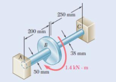
Fig. p3.55
(a)
The reaction at the supports.
Answer to Problem 55P
The reaction at the supports are
Explanation of Solution
Given information:
The modulus of rigidity of solid shafts is
Calculation:
The radius of the shaft AB is
The polar moment of inertia of shaft AB of radius
The torque carried by the shaft AB
Here,
Substitute
The radius of the shaft BC is
The polar moment of inertia of shaft BC of radius
The torque carried by the shaft BC
Here,
Substitute
The value of total torque in the shaft is
The total torque
Substitute
Substitute
Therefore, the reaction at the supports are
(b)
The maximum shearing stress in the shaft AB.
Answer to Problem 55P
The maximum shearing stress in the shaft AB is
Explanation of Solution
Given information:
The modulus of rigidity of solid shafts is
Calculation:
Refer (a).
The value of torque in the shaft AB is
The polar moment of inertia of shaft AB of radius
The maximum shearing stress in the shaft AB
Substitute
Therefore, the maximum shearing stress in the shaft AB is
(c)
The maximum shearing stress in the shaft BC.
Answer to Problem 55P
The maximum shearing stress in the shaft BC is
Explanation of Solution
Given information:
The modulus of rigidity of solid shafts is
Calculation:
Refer (a).
The value of torque in the shaft BC is
The polar moment of inertia of shaft BC of radius
The maximum shearing stress in the shaft BC
Substitute
Therefore, the maximum shearing stress in the shaft BC is
Want to see more full solutions like this?
Chapter 3 Solutions
Mechanics of Materials, 7th Edition


- 3.11 Knowing that each of the shafts AB, BC, and CD consists of a solid circular rod, determine (a) the shaft in which the maximum shear- ing stress occurs, (b) the magnitude of that stress. 48 N. m 144 N. m A Fig. P3.11 and P3.12 dAB 60 Nm B = 15 mm dBC C = 18 mm D dcp = 21 mmarrow_forward3.48 The design of the gear-and-shaft system shown requires that steel shafts of the same diameter be used for both AB and CD. It is further required that 7ma60 MPa and that the angle d, through which end D of shaft CD rotates not exceed 1.5. Knowing that G = 77.2 GPa, determine the required diamcter of the shafts. 40 mm 1000 N m 100 mm 400 mm 600 mm Fig. P3.48arrow_forwardPROBLEM 3.52 A 4 kNm torque T is applied at end A of the composite shaft shown. Knowing that the shear modulus is 77 GPa for the steel and 27 GPa for the aluminium, determine (a) the maximum shear stress in the steel core, (b) the maximum shear stress in the aluminium jacket, and (c) the angle of twist at A. [Ans. (a) 73.6 MPa (b) 34.4 MPa (c) 5.07°] 72 mm 54 mm 2.5 m Steel core Aluminium jackeť Fig. P3.52 and P3.53 22:37 e dx D 14/04/2022 BANG & OLUFSEN 40 delete home end pg up pg dn num backspace lock W ERT U %23 home og up 4.arrow_forward
- PROBLEM 3.52 A 4 kNm torque T is applied at end A of the composite shaft shown. Knowing that the shear modulus is 77 GPa for the steel and 27 GPa for the aluminium, determine (a) the maximum shear stress in the steel core, (b) the maximum shear stress in the aluminium jacket, and (c) the angle of twist at A. [Ans. (a) 73.6 MPa (b) 34.4 MPa (c) 5.07°] Hint: angle of twist at 72 mm end A is same for core and jacket 54 mm A 2.5 m Steel core Aluminium jacket Fig. P3.52 and P3.53 22:35 BANG & OLUFSEN delete home end og up pg dn num backspace 4 lock Q WE T U 080 home pg uparrow_forward3.38 The aluminum rod AB (G = 27 GPa) is bonded to the brass rod BD (G = 39 GPa). Knowing that portion CD of the brass rod is hollow and has an inner diameter of 40 mm, determine the angle of twist at A. 60 mm T = 1600 N m 36 mm TA = S00 N - mn 250 mm B 375 mm A 400 mm Fig. P3.38arrow_forward3.23 Under normal operating conditions a motor exerts a torque of magnitude T: at F. The shafts are made of a steel for which the allowable shearing stress is 82 MPa and have diameters dcDE = 24 mm and dran = 20 mm. Knowing that rp = 165 mm and rg = 114 mm, determine the largest allowable value of Tr. F. C T; B TEV E Fig. P3.23arrow_forward
- 3.33 (a) For the solid steel shaft shown, determine the angle of twist at A. Use G = 77 GPa. (b) Solve part a, assuming that the steel shaft is hollow with a 15 mm outer radius and a 10 mm inner radius. 15 mm A 1.8 m T = 250 N. m Fig. P3.33arrow_forward3.5 A torque T = 3 kN • m is applied to the solid bronze cylinder shown. Determine (a) the maximum shearing stress, (b) the shear- ing stress at point D, which lies on a 15-mm-radius circle drawn on the end of the cylinder, (e) the percent of the torque carried by the portion of the cylinder within the l15-mm radius. 60 mm 30 mm T=3 kN- m - 200 min Fig. P3.5arrow_forwardQ2/ The torques shown, in Fig. 2, are exerted on pulleys A and B. Knowing that the shafts are solid and made of steel (G=77 GPa), determine the maximum shear stress (t) of shaft BC, and then find the total angle of twist (0) between A and C. Fig. 2 TA Ta 300 N-m 30 mm 400 N-m 46 mm 0.9 m 0.75 m c!arrow_forward
- 3.42 The angle of rotation of end A of the gear-and-shaft system shown must not exceed 4°. Knowing that the shafts are made of a steel for which Tall = 65 MPa and G = 77.2 GPa, determine the largest torque T that can be safely applied at end A. 30 mm B Tahap 60 mm 90 mm 30 mm 0.2 m 0.4 m 0.2 m 0.1 m 0.5 marrow_forward5.86 The cast iron inverted T-section supports two concentrated loads of magni- tude P. The working stresses are 48 MPa in tension, 140 MPa in compression, and 30 MPa in shear. (a) Show that the neutral axis of the cross section is located at d = 48.75 mm and that the moment of inertia of the cross-sectional area about this axis is I = 11.918 x 106 mm“. (b) Find the maximum allowable value of P. 1.0 m 1.0 m 15 mm 3 m 150 mm NA- d 15 mm 150 mm FIG. P5.86arrow_forward1. The member BD is attached to a rod at B, to a hydraulic cylinder at C, and to a fixed support at D. The bolt used at D acts in double shear and is made from a steel for which the maximum allowable shearing stress is Tallow = 40 ksi. The rod AB is made of a steel for which the maximum allowable tensile stress is Oallow = 60 ksi. The upward hydraulic force applied at C is 12 kip. 1) Calculate the minimum diameter of the rod AB. 2) Calculate the minimum diameter of the bolt at D. B FAB 12 kip 8 in. FBDarrow_forward
 Elements Of ElectromagneticsMechanical EngineeringISBN:9780190698614Author:Sadiku, Matthew N. O.Publisher:Oxford University Press
 Mechanics of Materials (10th Edition)Mechanical EngineeringISBN:9780134319650Author:Russell C. HibbelerPublisher:PEARSON
 Thermodynamics: An Engineering ApproachMechanical EngineeringISBN:9781259822674Author:Yunus A. Cengel Dr., Michael A. BolesPublisher:McGraw-Hill Education
 Control Systems EngineeringMechanical EngineeringISBN:9781118170519Author:Norman S. NisePublisher:WILEY
 Mechanics of Materials (MindTap Course List)Mechanical EngineeringISBN:9781337093347Author:Barry J. Goodno, James M. GerePublisher:Cengage Learning
 Engineering Mechanics: StaticsMechanical EngineeringISBN:9781118807330Author:James L. Meriam, L. G. Kraige, J. N. BoltonPublisher:WILEY