
Mechanics of Materials, 7th Edition
7th Edition
ISBN: 9780073398235
Author: Ferdinand P. Beer, E. Russell Johnston Jr., John T. DeWolf, David F. Mazurek
Publisher: McGraw-Hill Education
expand_more
expand_more
format_list_bulleted
Concept explainers
Videos
Textbook Question
Chapter 3.8, Problem 92P
The solid circular shaft shown is made of a steel that is assumed to be elastoplastic with τY = 145 MPa. Determine the magnitude T of the applied torques when the plastic zone is (a) 16 mm deep, (b) 24 mm deep.
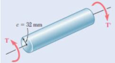
Fig. P3.92
Expert Solution & Answer
Want to see the full answer?
Check out a sample textbook solution
Students have asked these similar questions
When a bar with the hexagonal cross section
shown in Fig. (a) is subjected to a torque T,
numerical analysis shows that the maximum
shear stress in the bar is Tmax =
5.7T|3.
Determine the percentage loss in strength that
results when a circular bar of diameter dis
machined into the hexagonal shape shown in
Fig. (b).
Location of Tmax-
(a)
(b)
FIG. P3.53
The solid circular shaft shown is made of a steel that is assumed to be elastoplastic with 7y= 145 MPa. Determine the magnitude Tof
the applied torques when the plastic zone is 20 mm deep.
c = 32 mm
T
The magnitude T of the applied torques is 9830 kN.m.
Equal torques T = 5 kip · ft are applied to the two
steel bars with the cross sections shown. (Note
that the cross-sectional areas of the bars are
equal.) The length of each bar is 8 ft. Calculate
the maximum shear stress and angle of twist for
each bar. Use G= 12 × 10° psi for steel.
5 in.
10 in.
2 in.
1.0 in.
(a)
(b)
FIG. P3.52
Chapter 3 Solutions
Mechanics of Materials, 7th Edition
Ch. 3.1 - Determine the torque T that causes a maximum...Ch. 3.1 - For the cylindrical shaft shown, determine the...Ch. 3.1 - (a) Determine the torque T that causes a maximum...Ch. 3.1 - (a) Determine the maximum shearing stress caused...Ch. 3.1 - (a) For the 3-in.-diameter solid cylinder and...Ch. 3.1 - Fig. P3.6 3.6 A torque T=3 kN m is applied to the...Ch. 3.1 - The solid spindle AB is made of a steel with an...Ch. 3.1 - The solid spindle AB has a diameter ds = 1.5 in....Ch. 3.1 - Fig. P3.9 and P3.10 3.10 The shafts of the pulley...Ch. 3.1 - Knowing that each of the shafts AB, BC, and CD...
Ch. 3.1 - Fig. P3.11 and P3.12 3.12 Knowing that an...Ch. 3.1 - Under normal operating conditions, the electric...Ch. 3.1 - In order to reduce the total mass of the assembly...Ch. 3.1 - The allowable shearing stress is 15 ksi in the...Ch. 3.1 - The allowable shearing stress is 15 ksi in the...Ch. 3.1 - The solid shaft shown is formed of a brass for...Ch. 3.1 - Solve Prob. 3.17 assuming that the direction of Tc...Ch. 3.1 - The solid rod AB has a diameter dAB= 60 mm and is...Ch. 3.1 - Fig. P3.19 and P3.20 3.20 The solid rod AB has a...Ch. 3.1 - A torque of magnitude T = 1000 N m is applied at D...Ch. 3.1 - Fig. P3.21 and P3.22 3.22 A torque of magnitude T...Ch. 3.1 - Under normal operating conditions a motor exerts a...Ch. 3.1 - Fig P3.23 and P3.24 3.24 Under normal operating...Ch. 3.1 - Prob. 25PCh. 3.1 - Fig. P3.25 and P3.26 3.26 The two solid shafts are...Ch. 3.1 - For the gear train shown, the diameters of the...Ch. 3.1 - Fig. P3.27 and P3.28 3.28 A torque T = 900 N m is...Ch. 3.1 - Fig. P3.29 3.29 While the exact distribution of...Ch. 3.1 - Fig. P3.30 3.30 (a) For a given allowable shearing...Ch. 3.3 - Determine the largest allowable diameter of a...Ch. 3.3 - The ship at A has just started to drill for oil on...Ch. 3.3 - (a) For the solid steel shaft shown, determine the...Ch. 3.3 - (a) For the aluminum pipe shown (G = 27 GPa),...Ch. 3.3 - The electric motor exerts a 500 N m-torque on the...Ch. 3.3 - The torques shown are exerted on pulleys and B....Ch. 3.3 - The aluminum rod BC (G = 26 GPa) is bonded to the...Ch. 3.3 - The aluminum rod AB (G = 27 GPa) is bonded to the...Ch. 3.3 - The solid spindle AB has a diameter ds = 1.75 in....Ch. 3.3 - Fig. p3.39 and p3.40 3.40 The solid spindle AB has...Ch. 3.3 - Two shafts, each of 78in. diameter, are connected...Ch. 3.3 - Two solid steel shafts each of 30-mm diameter, are...Ch. 3.3 - A coder F, used to record in digital form the...Ch. 3.3 - Fig. p3.43 3.44 For the gear train described in...Ch. 3.3 - The design specifications of a 1.2-m-long solid...Ch. 3.3 - 3.46 and 3.47 The solid cylindrical rod BC of...Ch. 3.3 - 3.46 and 3.47 The solid cylindrical rod BC of...Ch. 3.3 - The design of the gear-and-shaft system shown...Ch. 3.3 - The electric motor exerts a torque of 900 Nm on...Ch. 3.3 - A hole is punched at A in a plastic sheet by...Ch. 3.3 - The solid cylinders AB and BC are bonded together...Ch. 3.3 - Solve Prob. 3.51, assuming that cylinder AB is...Ch. 3.3 - The composite shaft shown consists of a...Ch. 3.3 - Fig. p3.53 and p3.54 3.54 The composite shaft...Ch. 3.3 - Two solid steel shafts (G = 77.2 GPa) are...Ch. 3.3 - Solve Prob. 3.55, assuming that the shaft AB is...Ch. 3.3 - 3.57 and 3.58 Two solid steel shafts are fitted...Ch. 3.3 - 3.57 and 3.58 Two solid steel shafts are fitted...Ch. 3.3 - The steel jacket CD has been attached to the...Ch. 3.3 - A torque T is applied as shown to a solid tapered...Ch. 3.3 - Prob. 61PCh. 3.3 - A solid shaft and a hollow shaft are made of the...Ch. 3.3 - An annular plate of thickness t and modulus G is...Ch. 3.5 - Determine the maximum shearing stress in a solid...Ch. 3.5 - Determine the maximum shearing stress in a solid...Ch. 3.5 - Using an allowable shearing stress of 4.5 ksi,...Ch. 3.5 - Using an allowable shearing stress of 50 MPa,...Ch. 3.5 - While a steel shaft of the cross section shown...Ch. 3.5 - Determine the required thickness of the 50-mm...Ch. 3.5 - A steel drive shaft is 6 ft long and its outer and...Ch. 3.5 - The hollow steel shaft shown (G = 77.2 GPa, all =...Ch. 3.5 - A steel pipe of 3.5-in. outer diameter is to be...Ch. 3.5 - 3.73 The design of a machine element calls for a...Ch. 3.5 - Three shafts and four gears are used to form a...Ch. 3.5 - Three shafts and four gears are used to form a...Ch. 3.5 - The two solid shafts and gears shown are used to...Ch. 3.5 - Fig. P3.76 and P3.77 3.77 The two solid shafts and...Ch. 3.5 - The shaft-disk-belt arrangement shown is used to...Ch. 3.5 - A 5-ft-long solid steel shaft of 0.875-in....Ch. 3.5 - A 2.5-m-long steel shaft of 30-mm diameter rotates...Ch. 3.5 - The design specifications of a 1.2-m-long solid...Ch. 3.5 - A 1.5-m-long tubular steel shaft (G = 77.2 GPa) of...Ch. 3.5 - Fig. P3.82 and P3.83 3.83 A 1.5-m-long tubular...Ch. 3.5 - The stepped shaft shown must transmit 40 kW at a...Ch. 3.5 - The stepped shaft shown rotates at 450 rpm....Ch. 3.5 - Knowing that the stepped shaft shown transmits a...Ch. 3.5 - The stepped shaft shown must rotate at a frequency...Ch. 3.5 - Fig. P3.87 and P3.88 3.88 The stepped shaft shown...Ch. 3.5 - A torque of magnitude T = 200 lbin. is applied to...Ch. 3.5 - Fig. P3.89, P3.90 and P3.91 3.90 In the stepped...Ch. 3.5 - In the stepped shaft shown, which has a full...Ch. 3.8 - The solid circular shaft shown is made of a steel...Ch. 3.8 - Prob. 93PCh. 3.8 - Prob. 94PCh. 3.8 - Prob. 95PCh. 3.8 - Fig. P3.95 and P3.96 3.96 The solid shaft shown is...Ch. 3.8 - It is observed that a straightened paper clip can...Ch. 3.8 - The solid shaft shown is made of a mild steel that...Ch. 3.8 - Prob. 99PCh. 3.8 - Prob. 100PCh. 3.8 - Prob. 101PCh. 3.8 - Prob. 102PCh. 3.8 - Prob. 103PCh. 3.8 - Prob. 104PCh. 3.8 - A solid circular rod is made of a material that is...Ch. 3.8 - Prob. 106PCh. 3.8 - Prob. 107PCh. 3.8 - Prob. 108PCh. 3.8 - Prob. 109PCh. 3.8 - Prob. 110PCh. 3.8 - Prob. 111PCh. 3.8 - A 50-mm diameter cylinder is made of a brass for...Ch. 3.8 - Prob. 113PCh. 3.8 - The solid circular drill rod AB is made of a steel...Ch. 3.8 - Prob. 115PCh. 3.8 - Prob. 116PCh. 3.8 - After the solid shaft of Prob. 3.116 has been...Ch. 3.8 - The hollow shaft shown is made of a steel that is...Ch. 3.8 - Prob. 119PCh. 3.8 - Prob. 120PCh. 3.10 - Determine the smallest allowable square cross...Ch. 3.10 - Prob. 122PCh. 3.10 - Using all = 70 MPa and G = 27 GPa, determine for...Ch. 3.10 - Prob. 124PCh. 3.10 - Determine the largest torque T that can be applied...Ch. 3.10 - Each of the two brass bars shown is subjected to a...Ch. 3.10 - Prob. 127PCh. 3.10 - Prob. 128PCh. 3.10 - Prob. 129PCh. 3.10 - Shafts A and B are made of the same material and...Ch. 3.10 - Prob. 131PCh. 3.10 - Shafts A and B are made of the same material and...Ch. 3.10 - Prob. 133PCh. 3.10 - Prob. 134PCh. 3.10 - Prob. 135PCh. 3.10 - A 36-kipin. torque is applied to a 10-ft-long...Ch. 3.10 - A 4-m-long steel member has a W310 60 cross...Ch. 3.10 - Prob. 138PCh. 3.10 - A 5-kipft torque is applied to a hollow aluminum...Ch. 3.10 - A torque T = 750 kNm is applied to the hollow...Ch. 3.10 - A 750-Nm torque is applied to a hollow shaft...Ch. 3.10 - 3.142 and 3.143 A hollow member having the cross...Ch. 3.10 - A hollow member having the cross section shown is...Ch. 3.10 - A 90-Nm torque is applied to a hollow shaft having...Ch. 3.10 - 3.145 and 3.146 A hollow member having the cross...Ch. 3.10 - 3.145 and 3.146 A hollow member having the cross...Ch. 3.10 - A cooling tube having the cross section shown is...Ch. 3.10 - A hollow cylindrical shaft was designed to have a...Ch. 3.10 - Equal torques are applied to thin-walled tubes of...Ch. 3.10 - A hollow cylindrical shaft of length L, mean...Ch. 3 - A steel pipe of 12-in. outer diameter is...Ch. 3 - A torque of magnitude T = 120 Nm is applied to...Ch. 3 - Fig. P3.152 3.153 Two solid shafts are connected...Ch. 3 - Prob. 154RPCh. 3 - Prob. 155RPCh. 3 - A torque of magnitude T = 4 kNm is applied at end...Ch. 3 - Ends A and D of the two solid steel shafts AB and...Ch. 3 - As the hollow steel shaft shown rotates at 180...Ch. 3 - Prob. 159RPCh. 3 - Prob. 160RPCh. 3 - Prob. 161RPCh. 3 - The shaft AB is made of a material that is...
Knowledge Booster


Learn more about
Need a deep-dive on the concept behind this application? Look no further. Learn more about this topic, mechanical-engineering and related others by exploring similar questions and additional content below.Similar questions
- (a) Determine the largest torque that can be safely applied to the rectangular steel bar if the Compute the corresponding angle of twist using G= 80 GPa for steel. maximum shear stress is limited to 120 MPa. (b) %3D 20 mm S00 mm FIG. P3.49arrow_forward3.44 An aluminum tube with the hexagonal cross section shown is 2.5 ft long and has a constant wall thickness of 0.080 in. Find (a) the largest torque that the tube can carry if the shear stress is limited to 7200 psi; and (b) the angle of twist caused by this torque. Use G 4 x 10 psi for aluminum. -15 in - 0.075 in FIG. P3.44arrow_forward3.39 The solid spindle AB has a diameter d. = 40 mm and is made of a steel with G = 77 GPa and Tal = 120 MPa, while sleeve C) is made of a brass with G = 39 GPa and Ln = 70 MPa, Determine (a) the largest torque T that can be applied at A if the given allow- able stresses are not to be exceeded and if the angle of twist of sleeve CD is not to exceed 0.375°, (b) the corresponding angle through which end A rotates. %3D 70 MPa. Determine %3D B - 15 mm 200 mm = 6 mm D 100 mm A T Fig. P3.39arrow_forward
- Q2/ The torques shown, in Fig. 2, are exerted on pulleys A and B. Knowing that the shafts are solid and made of steel (G=77 GPa), determine the maximum shear stress (t) of shaft BC, and then find the total angle of twist (0) between A and C. Fig. 2 TA Ta 300 N-m 30 mm 400 N-m 46 mm 0.9 m 0.75 m c!arrow_forward1. A steel shaft is subjected to the torques shown. The shaft is solid with a diameter of 1 in and G = 12,000 ksi. Determine: (a) internal torque (lb ft) in each segment. Include the necessary diagram to show these internal forces (b) maximum shear stress (psi) in each segment (c) rotation angle of pulley D w/r to the support of A. Follow the rule of signs given in the lecture. Include the necessary FBDs of sections.arrow_forward3.33 (a) For the solid steel shaft shown, determine the angle of twist at A. Use G = 77 GPa. (b) Solve part a, assuming that the steel shaft is hollow with a 15 mm outer radius and a 10 mm inner radius. 15 mm A 1.8 m T = 250 N. m Fig. P3.33arrow_forward
- A brass rod 8mm diameter and 400mm long fits centrally inside aluminum tube of the same length having an external diameter of 16mm and a wall thickness of 3mm. The rod and tube are rigidly connected at their ends so that they twist together when a torque of 20 Nm is applied. Galuminum = 30GPa; Gbrass = 40GPa. Determine: a) The values of the torsional stiffness for the rod and the tube b) The torque transmitted by each c) The maximum shear stress in each d) The angle of twistarrow_forwardA hollow circular tube with a 2.3-cm I.D. and 2.5-cm O.D. is rigidly supported at its ends. A 2.5 kN-m torque is applied at the center of this tube. What is the maximum shear stress acting on this tube?arrow_forwardPROBLEM 2. A circular shaft AB consists of a 250 mm long, 22 mm diameter steel 125 mm cylinder which is 125 mm long and a 16mm diameter cavity has 125 mm been drilled from the other end B. The shaft is attached to fixed supports at both ends and a 120 N-m torque is applied at its mid- A section. a) Determine the torque exerted on the shaft at A. 120 N.m b) Determine the torque exerted on the shaft at B.arrow_forward
- 3.33 (a) For the solid steel shaft shown, determine the angle of twist at A. Use G = 11.2 × 10° psi. (b) Solve part a, assuming that the steel shaft is hollow with a 1.5-in. outer radius and a 0.75-in. inner radius. Fig. P3.32 1.5 in. A 3 ft T = 60 kip - in. %3D Fig. P3.33arrow_forwardThe solid circular drill rod AB is made of a steel that is assumed to be elastoplastic with TY = 22 ksi and G = 11.2 x 10⁶ psi. Knowing that a torque T = 73 kip-in. is applied to the rod and then removed, determine the permanent angle of twist of the rod. The permanent angle of twist of the rod isarrow_forward5. The torques shown are exerted on pulleys A and B. The diameter of the shaft AB is dAB = 50mm while the di- ameter of the shaft BC is dBC = 66mm. The torque at A is TA = 500Nm while the torque at B is TB = 600N . Knowing that both shafts are solid, determine the maxi- mum sharing stress in shaft AB and shaft BC. Barrow_forward
arrow_back_ios
SEE MORE QUESTIONS
arrow_forward_ios
Recommended textbooks for you
 Elements Of ElectromagneticsMechanical EngineeringISBN:9780190698614Author:Sadiku, Matthew N. O.Publisher:Oxford University Press
 Mechanics of Materials (10th Edition)Mechanical EngineeringISBN:9780134319650Author:Russell C. HibbelerPublisher:PEARSON
 Thermodynamics: An Engineering ApproachMechanical EngineeringISBN:9781259822674Author:Yunus A. Cengel Dr., Michael A. BolesPublisher:McGraw-Hill Education
 Control Systems EngineeringMechanical EngineeringISBN:9781118170519Author:Norman S. NisePublisher:WILEY
 Mechanics of Materials (MindTap Course List)Mechanical EngineeringISBN:9781337093347Author:Barry J. Goodno, James M. GerePublisher:Cengage Learning
 Engineering Mechanics: StaticsMechanical EngineeringISBN:9781118807330Author:James L. Meriam, L. G. Kraige, J. N. BoltonPublisher:WILEY
Elements Of Electromagnetics
Mechanical Engineering
ISBN:9780190698614
Author:Sadiku, Matthew N. O.
Publisher:Oxford University Press
Mechanics of Materials (10th Edition)
Mechanical Engineering
ISBN:9780134319650
Author:Russell C. Hibbeler
Publisher:PEARSON
Thermodynamics: An Engineering Approach
Mechanical Engineering
ISBN:9781259822674
Author:Yunus A. Cengel Dr., Michael A. Boles
Publisher:McGraw-Hill Education
Control Systems Engineering
Mechanical Engineering
ISBN:9781118170519
Author:Norman S. Nise
Publisher:WILEY
Mechanics of Materials (MindTap Course List)
Mechanical Engineering
ISBN:9781337093347
Author:Barry J. Goodno, James M. Gere
Publisher:Cengage Learning
Engineering Mechanics: Statics
Mechanical Engineering
ISBN:9781118807330
Author:James L. Meriam, L. G. Kraige, J. N. Bolton
Publisher:WILEY
Everything About COMBINED LOADING in 10 Minutes! Mechanics of Materials; Author: Less Boring Lectures;https://www.youtube.com/watch?v=N-PlI900hSg;License: Standard youtube license