
Concept explainers
Videos
A 4-m-long steel member has a W310 × 60 cross section. Knowing that G = 77.2 GPa and that the allowable shearing stress is 40 MPa, determine (a) the largest torque T that can be applied, (b) the corresponding angle of twist. Refer to Appendix C for the dimensions of the cross section and neglect the effect of stress concentrations. (Hint: consider the web and flanges separately and obtain a relation between the torques exerted on the web and a flange, respectively, by expressing that the resulting angles of twist are equal.)
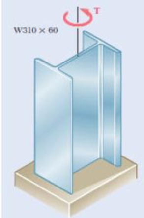
Fig. P3.137
(a)
Find the largest torque (T) that can be applied.
Answer to Problem 137P
The largest torque (T) is
Explanation of Solution
Given information:
The length of the steel member (L) is
The provided section of the member is
The allowable shearing stress
The modulus rigidity of the steel (G) is
Assume the angle of twist in flange and web is equal.
Calculation:
Consider flange:
Refer Appendix C, “Properties of Rolled-Steel shapes”.
The width of the flange (a) is
The thickness of the flange (b) is
Calculate the ratio of width to thickness of the steel
Substitute
Hence, the ratio of
Calculate the ratio of thickness to width of the steel
Substitute
Calculate the coefficient for rectangular bar
Substitute 0.0645 for
Calculate the angle of twist in flange
Here,
Substitute 0.31979 for
Consider web:
Refer Appendix C, “Properties of Rolled-Steel shapes”.
The thickness of the web (b) is
The depth of the member (D) is
Calculate the width of the web (a) using the formula:
Here,
Substitute
Calculate the ratio of width to thickness of the steel
Substitute
Hence, the ratio of
Calculate the ratio of thickness to width of the steel
Substitute
Calculate the coefficient for rectangular bar
Substitute 0.02716 for
Calculate the angle of twist in web
Substitute 0.32763 for
Since the angle of twist in flange and web is equal, therefore,
Substitute
By taking the sum of torque exerted on two flanges and web in the member is equal to the total torque T applied to member. Therefore,
Substitute
Substitute
Calculate the torque in the flange
Substitute
Substitute
Calculate the torque in the web
Substitute
Substitute
Hence, take the lesser value from the torque produced in flange and web respectively.
Therefore, the largest torque (T) is
(b)
Find the angle
Answer to Problem 137P
The angle
Explanation of Solution
Given information:
The length of the steel member (L) is
The provided section of the member is
The allowable shearing stress
The modulus rigidity of the steel (G) is
Assume the angle of twist in flange and web is equal.
Calculation:
From the above calculation of angle of twist, take the critical angle to compute the angle of twist.
Calculate the angle of twist
Substitute
Therefore, the angle of twist of the section is
Want to see more full solutions like this?
Chapter 3 Solutions
Mechanics of Materials, 7th Edition


- 1. A steel shaft is subjected to the torques shown. The shaft is solid with a diameter of 1 in and G = 12,000 ksi. Determine: (a) internal torque (lb ft) in each segment. Include the necessary diagram to show these internal forces (b) maximum shear stress (psi) in each segment (c) rotation angle of pulley D w/r to the support of A. Follow the rule of signs given in the lecture. Include the necessary FBDs of sections.arrow_forwardA steel shaft is to be manufactured either as a solid circular or as circular tube. The shaft is required to transmit a torque of 1200 Nm without exceeding an allowable shear stress of 40 MPa, nor an allowable rate of twist of 0.75º/m. For G = 78GPa, determine: The required diameter do of the solid shaft. The required outer diameter d2 of the hollow shaft if the thickness t of the shaft is specified as one-tenth of the outer diameter. The ratio of diameters (that is, the ratio d2/do and the ratio of the weights of the hollow and solid shafts.arrow_forwardProblem 2: A shaft is to be fitted with a flanged coupling having 6 bolts on a circle of diameter 150 mm and 4 bolts on a circle of diameter 100 mm. The shaft may be subjected to either a direct tensile load of 400 kN or a twisting moment of 18 kN-m. If the maximum direct tensile and shearing stresses permissible in the bolt material are 125 MPa and 55 MPa respectively. Find the minimum diameter of the bolt required. Assume that each bolt takes an equal share of the load or torque. Outer bolt Shaft circle Shaft Bolt Inner bolt Flange circlearrow_forward
- The diameter of and LcD = 240 mm. 1. The lengths LAB = LBC = 200 mm parts AB and CD of the bar is 25 mm and the diameter of part BC is 50 mm. The shear modulus of the material is G = 80 GPa. If the torque T = 2.2 kN- m, determine the magnitude of the angle of twist of the right end of the bar relative to the wall in degrees. 4 kN-m 8 kN-m LAB. LBC. 2. The lengths LAB = LBC = 200 mm and LCD = 240 mm. The diameter of parts AB and CD of the bar is 25 mm and the diameter of part BC is 50 mm. The shear modulus of the material is G = 80 GPa. What value of the torque T would cause the angle of twist of the right end of the bar relative to the wall to be zero? 4 kN-m 8 kN-m LAB. T LBCarrow_forwardA flanged bolt coupling consists of six - in. steel bolts evenly spaced around a bolt circle of 14-in. in diameter, and four- in. steel bolts on a concentric bolt circle of 10-in. in diameter. What torque can be applied without exceeding a shearing stress of 8500 psi in the steel and 6500 psi in the aluminum? Assume Gs = 12 x 10° psi and G, = 4x 10⁶ psi.arrow_forwardSix 30 mm diameter bolts in the outer bold circle of 370 mm radius are steel A T and six 20 mm diameter bolt in the inner bolt circle of 260 mm diameter are aluminum. What is the torque capacity of the coupling? Assume that the allowable shearing stress for the steel bolts is 40 Mpa and aluminum bolts of 30 Mpa. The Shear modulus of elasticity of aluminum and steel are 28 Gpa and 84 Gpa, respectively. P2 P1 R2 R1 1. 757 T°C Despejado A GGn G8/11/202 O Escribe aquí para buscar acerarrow_forward
- The end of a 2.5 in diameter steel shaft is milled to two flats (one flat on the top and one flat at the bottom) to permit the use of a hand crank. Each flat is located 1.00 in from the center of the shaft. A torque of 750 Ib-in is applied. Find: (a) the maximum shear stress at the end of the shaft with two flats in psi unit. (b) the angle of twist in fadians (c) the angle of twist in degrees h= 1.0 in h= 1.0 in d= 2.50 in Show all your calculations.arrow_forward1. The 12 kN m torque is applied to the free end of the 6-m steel shaft. The angle of rotation of the shaft is to be limited to 3°. (a) Find the diameter d of the smallest shaft that can be used. (b) What will be the maximum shear stress in the shaft? Use G = 83 GPa for steel. 2. The compound shaft is attached to a rigid wall at each end. For the bronze segment AB, the diameter is 75 mm and G = 35 GPa. For the steel segment BC, the diameter is 50 mm and G = 83 GPa. Given that a = 2 m and b = 1.5 m, compute the largest torque T that can be applied as shown in the figure if the maximum shear stress is limited to 60 MPa in the bronze and 80 MPa in the steel. 75 mm 50 mm A Bronze B Steelarrow_forwardFor a given maximum average shear stress, determine the factor by which the torque-carrying capacity is increased if the half-circular section is reversed from the dashed-line position to the section shown. The tube is 0.1 in. thick.arrow_forward
- The hollow rod BC has a length of 100 mm and an outer diameter of 40 mm Q4) and is made of aluminum with G = 27 GPa. Rod AB is solid and has a length of 80 mm and a diameter of 30 mm and is made of brass with G = 41 GPa. The assembly undergoes a torque T at A. If the maximum shearing stresses at both parts AB and BC are the same, (a) determine the inner diameter of rod BC. (b) If the allowable shearing stress is 50 MPa, determine the largest torque that can be applied at A. (c) Determine the rotation angle of end A when the torque computed at part (b) is applied. Aluminum -Brass T B Aarrow_forwardTwo steel springs arranged in series supports a load P. The upper spring has 12 turns of 20-mm-diameterwire on a mean radius of 100 mm. The lower spring consists of 10 turns of 25-mm diameter wire on amean radius of 75 mm. If the maximum shearing stress in either spring must not exceed 300 MPa,compute the maximum value of P and the total elongation of the assembly. Use approximation formulaand G = 83 GPa. Compute the equivalent spring constant by dividing the load by the total elongation.arrow_forwardE' 3. For the 3-in.-diameter solid cylinder and loading shown, T = 40 kip-in., determine: (a) the polar moment of inertia, (b) the maximum shearing stress, (c) the maximum shearing strain, and (d) the angle of twist d. Use G=77 GPa for the modulus of rigidity and the length of the rod as 10 ft. 3 in.arrow_forward
 Elements Of ElectromagneticsMechanical EngineeringISBN:9780190698614Author:Sadiku, Matthew N. O.Publisher:Oxford University Press
 Mechanics of Materials (10th Edition)Mechanical EngineeringISBN:9780134319650Author:Russell C. HibbelerPublisher:PEARSON
 Thermodynamics: An Engineering ApproachMechanical EngineeringISBN:9781259822674Author:Yunus A. Cengel Dr., Michael A. BolesPublisher:McGraw-Hill Education
 Control Systems EngineeringMechanical EngineeringISBN:9781118170519Author:Norman S. NisePublisher:WILEY
 Mechanics of Materials (MindTap Course List)Mechanical EngineeringISBN:9781337093347Author:Barry J. Goodno, James M. GerePublisher:Cengage Learning
 Engineering Mechanics: StaticsMechanical EngineeringISBN:9781118807330Author:James L. Meriam, L. G. Kraige, J. N. BoltonPublisher:WILEY