
Videos
A steel pipe of 12-in. outer diameter is fabricated from ¼-in.-thick plate by welding along a helix that forms an angle of 45° with a plane parallel to the axis of the pipe. Knowing that the maximum allowable tensile stress in the weld is 12 ksi, determine the largest torque that can be applied to the pipe.
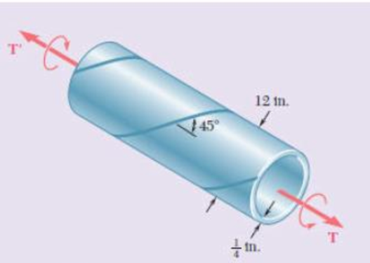
Fig. P3.151
Find the largest torque that can be applied to the pipe.
Answer to Problem 151RP
The largest torque that can be applied to the pipe is
Explanation of Solution
Given information:
The outer diameter of the steel pipe
The thickness of the steel pipe (t) is
The angle of the helix is
The maximum allowable tensile stress in the weld
Calculation:
Calculate the inner radius of the steel pipe
Substitute
Calculate the polar moment of inertia of steel pipe (J) as follows:
Here,
Substitute
The torsion formula for maximum shear stress in the solid shaft AB
Here, T is the applied internal torque.
Substitute
Therefore, the largest torque that can be applied to the pipe is
Want to see more full solutions like this?
Chapter 3 Solutions
Mechanics of Materials, 7th Edition


- 3.11 Knowing that each of the shafts AB, BC, and CD consists of a solid circular rod, determine (a) the shaft in which the maximum shear- ing stress occurs, (b) the magnitude of that stress. 48 N. m 144 N. m A Fig. P3.11 and P3.12 dAB 60 Nm B = 15 mm dBC C = 18 mm D dcp = 21 mmarrow_forwardA steel pipe of 400-mm outer diameter is fabricated from 10-mm-thick plate by welding along a helix that forms an angle of 20°with a plane perpendicular to the axis of the pipe. Knowing that the maximum allowable normal and shearing stresses in the directions respectively normal and tangential to the weld are σ = 60 MPa and τ = 36 MPa, determine the magnitude P of the largest axial force that can be applied to the pipe.arrow_forwardA steel pipe of 300-mm outer diameter is fabricated from an 8-mm-thick plate by welding along a helix that forms an angle of 20° with a plane perpendicular to the axis of the pipe. Knowing that a 250-kN axial force P and a 12-kN-m torque T. each directed as shown, are applied to the pipe, determine the normal and in-plane shearing stresses in directions, respectively, normal and tangential to the weld. T The normal stress is - The shear stress is- Weld 20⁰ 8 mm MPa MPa.arrow_forward
- 4. As for the relationship between normal stress and shear stress, it is correct that () (A) The normal stress and shear stress on the same section are perpendicular to each other; (B) The normal stress and shear stress on different sections are perpendicular to each other; (C) The normal stress and shear stress on the same section are parallel to each other; (D) The normal stress and shear stress on different sections are parallel to each other;arrow_forward3.39 The solid spindle AB has a diameter d. = 40 mm and is made of a steel with G = 77 GPa and Tal = 120 MPa, while sleeve C) is made of a brass with G = 39 GPa and Ln = 70 MPa, Determine (a) the largest torque T that can be applied at A if the given allow- able stresses are not to be exceeded and if the angle of twist of sleeve CD is not to exceed 0.375°, (b) the corresponding angle through which end A rotates. %3D 70 MPa. Determine %3D B - 15 mm 200 mm = 6 mm D 100 mm A T Fig. P3.39arrow_forwardIn the hanger shown the upper portion of link ABC is 9-mm thick and the lower portions are each 6-mm thick. Epoxy resin is used to bond the upper and lower portions together at B. The pin at A is of 9-mm diameter while a 6-mm-diameter pin is used at C. Determine (a) the shearing stress in pin A. (b) the shearing stress in pin C, (c) the largest normal stress in link ABC, (d) the average shearing stress on the bonded surfaces at B, (e) the bearing stress in the link at C. 30 mm 150 mm 40 mm 170 mm 240 mm 2400 N 120 marrow_forward
- A steel pipe of 400-mm outer diameter is fabricated from 10-mmthick plate by welding along a helix that forms an angle of 20° with a plane perpendicular to the axis of the pipe. Knowing that a 300-kN axial force P is applied to the pipe, determine the normal and shearing stresses in directions respectively normal and tangential to the weld.arrow_forward2. A carbon steel ball with a 30-mm diameter is pressed against a flat carbon steel plate with a force of 20 N. Determine the maximum shear stress, and the depth in the plate at which it will occur.arrow_forwardQ2/ The torques shown, in Fig. 2, are exerted on pulleys A and B. Knowing that the shafts are solid and made of steel (G=77 GPa), determine the maximum shear stress (t) of shaft BC, and then find the total angle of twist (0) between A and C. Fig. 2 TA Ta 300 N-m 30 mm 400 N-m 46 mm 0.9 m 0.75 m c!arrow_forward
- 2. (a) A steel cylinder of 60 mm inner radius and 80 mm outer radius is subjected to an internal pressure of 30 MNm ². Determine the resulting hoop stress values at the inner and outer surfaces and graphically represent (sketch) the general form of hoop stress variation through the thickness of the cylinder wall. (b) (c) The cylinder in (a) is to be used as a shrink-fitted sleeve to strengthen a hydraulic cylinder manufactured of the same steel. The cylinder bore radius is 40 mm. When the hydraulic cylinder is not subjected to internal pressure, the interference pressure generated due to the shrink fit alone is 30 MNm2. Note: This is the same value of pressure as in the problem analysed in part (a). Determine the resulting hoop stress values at the inner and outer walls of the inner cylinder. Graphically represent the general form of hoop stress variation through the wall thickness in the combination indicating the key values as calculated in parts (a) and (b). (d) If the Young's…arrow_forward2.14 The aluminum rod ABC (E 10.1 × 10⁶ psi), which consists of two cylindrical portions AB and BC, is to be replaced with a cylin- drical steel rod DE (E = 29 × 106 psi) of the same overall length. Determine the minimum required diameter d of the steel rod if its vertical deformation is not to exceed the deformation of the aluminum rod under the same load and if the allowable stress in the steel rod is not to exceed 24 ksi. Ĵ 12 in. + 18 in. 28 kips -1.5 in. Fig. P2.14 B -2.25 in. 28 kips D E --arrow_forwardPROBLEM 1.3 3 in. 30 kips Two solid cylindrical rods AB and BC are welded together at B and loaded as shown. Determine the magnitude of the force P for which the tensile stress in rod AB is twice the magnitude of the compressive stress in rod BC. 30 kips 40 in PROBLEM 1.4 In Prob. 1.3, knowing that P = 40 kips, determine the average normal stress at the midsection of (a) rod AB, (b) rod BC.arrow_forward
 Elements Of ElectromagneticsMechanical EngineeringISBN:9780190698614Author:Sadiku, Matthew N. O.Publisher:Oxford University Press
 Mechanics of Materials (10th Edition)Mechanical EngineeringISBN:9780134319650Author:Russell C. HibbelerPublisher:PEARSON
 Thermodynamics: An Engineering ApproachMechanical EngineeringISBN:9781259822674Author:Yunus A. Cengel Dr., Michael A. BolesPublisher:McGraw-Hill Education
 Control Systems EngineeringMechanical EngineeringISBN:9781118170519Author:Norman S. NisePublisher:WILEY
 Mechanics of Materials (MindTap Course List)Mechanical EngineeringISBN:9781337093347Author:Barry J. Goodno, James M. GerePublisher:Cengage Learning
 Engineering Mechanics: StaticsMechanical EngineeringISBN:9781118807330Author:James L. Meriam, L. G. Kraige, J. N. BoltonPublisher:WILEY