
Fundamentals of Electric Circuits
6th Edition
ISBN: 9780078028229
Author: Charles K Alexander, Matthew Sadiku
Publisher: McGraw-Hill Education
expand_more
expand_more
format_list_bulleted
Concept explainers
Videos
Textbook Question
Chapter 2, Problem 28P
Design a problem, using Fig. 2.92, to help other students better understand series and parallel circuits.
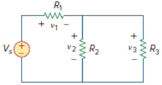
Figure 2.92
Expert Solution & Answer
Want to see the full answer?
Check out a sample textbook solution
Students have asked these similar questions
Circuits IShow you solution please
100
202
b. zero
OC. 50
A supermesh can be formed by combining two loops that contain a common voltage source.
Select one:
O True
O False
O Type here to search
INSTRUCTIONS: Solve the following problems. Show and COMPLETE solutions. Draw all CIRCUIT DIAGRAMS or the equivalent circuit (dummy circuit) as the case may be. Write your solutions on sheet/s of short bond paper.
A battery is to consist of 20 identical cells. The emf of each cell is 1.5 V and the internal resistance is 0.20 ohm. This battery will be used to supply power to a 10 ohm lamp. Determine the current on the lamp if:1. The 20 cells are connected in series 2. The 20 cells are connected in parallel 3. The 20 cells are arranged 5 cells in series in 4 parallel rows.
Chapter 2 Solutions
Fundamentals of Electric Circuits
Ch. 2.2 - The essential component of a toaster is an...Ch. 2.2 - For the circuit shown in Fig. 2.9, calculate the...Ch. 2.2 - A resistor absorbs an instantaneous power of 30...Ch. 2.3 - How many branches and nodes does the circuit in...Ch. 2.4 - Find v1 and v2 in the circuit of Fig. 2.22. Figure...Ch. 2.4 - Find vx and vo in the circuit of Fig. 2.24. Figure...Ch. 2.4 - Find vo and io in the circuit of Fig. 2.26. Figure...Ch. 2.4 - Find the current and voltages in the circuit shown...Ch. 2.6 - By combining the resistors in Fig.2.36, find Req....Ch. 2.6 - Find Rab for the circuit in Fig.2.39. Figure 2.39...
Ch. 2.6 - Calculate Geq in the circuit of Fig.2.41. Figure...Ch. 2.6 - Find v1 and v2 in the circuit shown in Fig. 2.43....Ch. 2.7 - Transform the wye network in Fig. 2.51 to a delta...Ch. 2.7 - For the bridge network in Fig. 2.54, find Rab and...Ch. 2.8 - Refer to Fig. 2.55 and assume there are six light...Ch. 2.8 - Following the ammeter setup of Fig. 2.61. design...Ch. 2 - The reciprocal of resistance is: (a) voltage (b)...Ch. 2 - Prob. 2RQCh. 2 - Prob. 3RQCh. 2 - The maximum current that a 2W, 80 k resistor can...Ch. 2 - Prob. 5RQCh. 2 - The current I in the circuit of Fig. 2.63 is: (a)...Ch. 2 - The current I0 of Fig. 2.64 is: (a) 4 A (b) 2 A...Ch. 2 - In the circuit in Fig. 2.65, V is: (a) 30 V (b) 14...Ch. 2 - Which of the circuit in Fig. 2.66 will give you...Ch. 2 - In the circuit of Fig. 2.67, a decrease in R3...Ch. 2 - Design a problem, complete with a solution, to...Ch. 2 - Find the hot resistance of a light bulb rated 60...Ch. 2 - A bar of silicon is 4 cm long with a circular...Ch. 2 - (a) Calculate current i in Fig. 2.68 when the...Ch. 2 - For the network graph in Fig. 2.69. find the...Ch. 2 - In the network graph shown in Fig. 2.70, determine...Ch. 2 - Determine the number of branches and nodes in the...Ch. 2 - Design a problem, complete with a solution, to...Ch. 2 - Find i1, i2, and i3 in Fig. 2.73. Figure 2.73 For...Ch. 2 - Determine i1 and i2 in the circuit of Fig. 2.74....Ch. 2 - In the circuit of Fig. 2.75, calculate V1 and V2....Ch. 2 - In the circuit in Fig. 2.76, obtain v1, v2, and...Ch. 2 - For the circuit in Fig. 2.77, use KCL to find the...Ch. 2 - Given the circuit in Fig. 2.78, use KVL to find...Ch. 2 - Calculate v and ix in the circuit of Fig. 2.79....Ch. 2 - Determine Vo in the circuit in Fig. 2.80. Figure...Ch. 2 - Obtain v1 through v3 in the circuit of Fig. 2.81....Ch. 2 - Find I and V in the circuit of Fig. 2.82. Figure...Ch. 2 - From the circuit in Fig. 2.83, find I, the power...Ch. 2 - Determine io in the circuit of Fig. 2.84. Figure...Ch. 2 - Find Vx in the circuit of Fig. 2.85. Figure 2.85...Ch. 2 - Find Vo in the circuit in Fig. 2.86 and the power...Ch. 2 - In the circuit shown in Fig. 2.87, determine Vx...Ch. 2 - For the circuit in Fig. 2.88, find Vo/Vs in terms...Ch. 2 - For the network in Fig. 2.89, find the current,...Ch. 2 - For the circuit in Fig. 2.90, io = 3 A. Calculate...Ch. 2 - Calculate Io in the circuit of Fig. 2.91. Figure...Ch. 2 - Design a problem, using Fig. 2.92, to help other...Ch. 2 - All resistors (R) in Fig. 2.93 are 10 each. Find...Ch. 2 - For the circuit in Fig. 2.95, determine i1 to i5....Ch. 2 - Find i1 through i4 in the circuit in Fig. 2.96....Ch. 2 - Obtain v and i in the circuit of Fig. 2.97. Figure...Ch. 2 - Using series/parallel resistance combination, find...Ch. 2 - Calculate Vo and Io in the circuit of Fig. 2.99....Ch. 2 - Find i and Vo in the circuit of Fig. 2.100. Figure...Ch. 2 - Given the circuit in Fig. 2.101 and that the...Ch. 2 - Find Req and io in the circuit of Fig. 2.102....Ch. 2 - Evaluate Req looking into each set of terminals...Ch. 2 - For the ladder network in Fig. 2.104, find I and...Ch. 2 - If Req = 50 in the circuit of Fig. 2.105, find R....Ch. 2 - Reduce each of the circuits in Fig. 2.106 to a...Ch. 2 - Calculate the equivalent resistance Rab at...Ch. 2 - For the circuits in Fig. 2.108, obtain the...Ch. 2 - Find the equivalent resistance at terminals a-b of...Ch. 2 - Find I in the circuit of Fig. 2.110. Figure 2.110Ch. 2 - Find the equivalent resistance Rab in the circuit...Ch. 2 - Convert the circuits in Fig. 2.112 from Y to ....Ch. 2 - Transform the circuits in Fig. 2.113 from to Y....Ch. 2 - Design a problem to help other students better...Ch. 2 - Obtain the equivalent resistance at the terminals...Ch. 2 - For the circuit shown in Fig. 2.116, find the...Ch. 2 - Obtain the equivalent resistance Rab in each of...Ch. 2 - Consider the circuit in Fig. 2.118. Find the...Ch. 2 - Calculate I0 in the circuit of Fig. 2.119. Figure...Ch. 2 - Determine V in the circuit of Fig. 2.120. Figure...Ch. 2 - Find Req and I in the circuit of Fig. 2.121....Ch. 2 - The 150 W tight bulb in Fig. 2.122 is rated at 110...Ch. 2 - If the three bulbs of Prob. 2.59 are connected in...Ch. 2 - As a design engineer, you are asked to design a...Ch. 2 - Prob. 62PCh. 2 - If an ammeter with an internal resistance of 100 ...Ch. 2 - The potentiometer (adjustable resistor) Rx in Fig....Ch. 2 - Design a circuit that uses a dArsonval meter (with...Ch. 2 - A 20-k/V voltmeter reads 10 V full scale. (a) What...Ch. 2 - (a) Obtain the voltage Vo in the circuit of Fig....Ch. 2 - (a) Find the current I in the circuit of Fig....Ch. 2 - A voltmeter used to measure Vo in the circuit in...Ch. 2 - (a) Consider the Wheatstone bridge shown in Fig....Ch. 2 - Figure 2.131 represents a model of a solar...Ch. 2 - Find Vo in the two-way power divider circuit in...Ch. 2 - An ammeter model consists of an ideal ammeter in...Ch. 2 - The circuit in Fig. 2.134 is to control the speed...Ch. 2 - Find Rab in the four-way power divider circuit in...Ch. 2 - Repeat Prob. 2.75 for the eight-way divider shown...Ch. 2 - Suppose your circuit laboratory has the following...Ch. 2 - In the circuit in Fig. 2.137, the wiper divides...Ch. 2 - Prob. 79CPCh. 2 - A loudspeaker is connected to an amplifier as...Ch. 2 - For a specific application, the circuit shown in...Ch. 2 - The pin diagram of a resistance array is shown in...Ch. 2 - Two delicate devices are rated as shown in Fig....
Knowledge Booster


Learn more about
Need a deep-dive on the concept behind this application? Look no further. Learn more about this topic, electrical-engineering and related others by exploring similar questions and additional content below.Similar questions
- ANSWER IN ESSAY FORM What is the purpose of Multisim in terms of circuit creation in relation to Ohms law, and what is the significance of Ohms law in our daily lives?arrow_forwardFind the RT(total resistance) and show complete solution.arrow_forward3- A junction where two (or) more than two network elements meet is known as a node 4- The algebraic sum of voltages around any closed path in a network is equal to one 5- The basic laws for analyzing an electric circuit are Newtons laws 6- Relation between currents according to KCL for a node with two input current (Ii & I2)and two outputs (I3 & I4) is I1-12+I3+14=0 7- A 3-ohm and 6-ohm resistor are connected in parallel, and a 10-ohm resistor is in series with the combination. When 36 volts is applied to the three resistors, the total current in the circuit is 2 amps. 8- KCL and KVL is limited to write two equations for a particular circuit. 9- When assigning branch currents, you need not be concerned with the direction you choose. 10- For the circuit shown below (Fig.1) the value of resistance is 17.5 ohms 5 ohm 2 A 70 v 7 ohm R ? Fig.1arrow_forward
- kindly help me with this problem thank you 1. Design a problem, complete with solution. Use at least three resistors and one voltage source. You may use the 3 resistors in any way you wish so long as the concepts of Ohm’s Law, Series and Parallel Circuits are discussed.arrow_forwardThe circuit below(left) displays a schematic diagram of a battery. The voltage measured by U1 is called the terminal voltage given R1 = 1 ohm. In the circuit below(right), the terminal voltage of each of the battery-resistor combination is VT = 1.5 volts. The current passing through R1, R2, R5arrow_forwardUse Kirchhoff's Law to solve for the current passing through each resistor. Compare it with what you got from the PHET Simulation A D 392 www 6V E www F 192 www 292 352 www 9V B Carrow_forward
- Q3: find the current through the 48ohm resistor in the circuit and assume the diode is silicon diode and the forward internal resistor of the diode is 1ohm. 10 V D₁ D4 (i) 48 Ω ww D2 D3arrow_forwardShow and COMPLETE solutions. Draw all CIRCUIT DIAGRAMS or the equivalent circuit (dummy circuit) as the case may be. A battery is to consist of 20 identical cells. The emf of each cell is 1.5 V and the internal resistance is 0.20 ohm. This battery will be used to supply power to a 10-ohm lamp. Determine thecurrent on the lamp if: The 20 cells are arranged 5 cells in series in 4 parallel rows.arrow_forwardI want the solution Q2/ Q3/ Q4/arrow_forward
- Consider a PV Module with 8 PV cells with the Size of each 10cm x 5cm are connected in series. Calculate the following for the above Module. a. The output voltage is 4V, the output power is 6W b. The output voltage is 4V, the output power is 8W c. The output voltage is 8V, the output power is 1.5W d. The output voltage is 8V, the output power is 6Warrow_forward2- Give a definition of ohm's law for the three relationships between V, I and R. Use the terin "proportional" and "inverse proportional ", and also state the conditions for each individual relationship.arrow_forwardIf we want to connect a voltage source with two resistors (either in series or in parallel) then voltage drop across the resistor R1 and the voltage across the resistor R2 (if R, = R,=102) will be the same whether they are connected in series or in parallel. Select one: O True O False ere to searcharrow_forward
arrow_back_ios
SEE MORE QUESTIONS
arrow_forward_ios
Recommended textbooks for you
 Delmar's Standard Textbook Of ElectricityElectrical EngineeringISBN:9781337900348Author:Stephen L. HermanPublisher:Cengage Learning
Delmar's Standard Textbook Of Electricity
Electrical Engineering
ISBN:9781337900348
Author:Stephen L. Herman
Publisher:Cengage Learning
Electrical Measuring Instruments - Testing Equipment Electrical - Types of Electrical Meters; Author: Learning Engineering;https://www.youtube.com/watch?v=gkeJzRrwe5k;License: Standard YouTube License, CC-BY
01 - Instantaneous Power in AC Circuit Analysis (Electrical Engineering); Author: Math and Science;https://www.youtube.com/watch?v=If25y4Nhvw4;License: Standard YouTube License, CC-BY