
Concept explainers
Videos
For a specific application, the circuit shown in Fig. 2.140 was designed so that IL = 83.33 mA and that Rin = 5 kΩ. What are the values of R1 and R2?
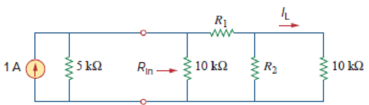
Figure 2.140
Calculate the values of
Answer to Problem 81CP
The values of
Explanation of Solution
Given Data:
Refer to Figure 2.140 in the textbook for the given circuit.
Formula used:
Consider the expression for
Here,
Consider the expression for
Calculation:
Modify Figure 2.140 as shown in Figure 1.
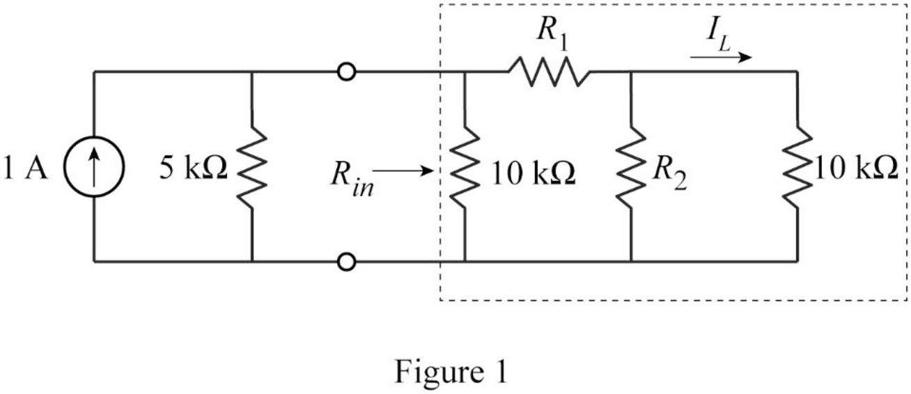
In Figure 1,
Therefore,
From Figure 1, write the expression for equivalent resistance
Substitute
To maintain
Modify the Figure as shown in Figure 2.
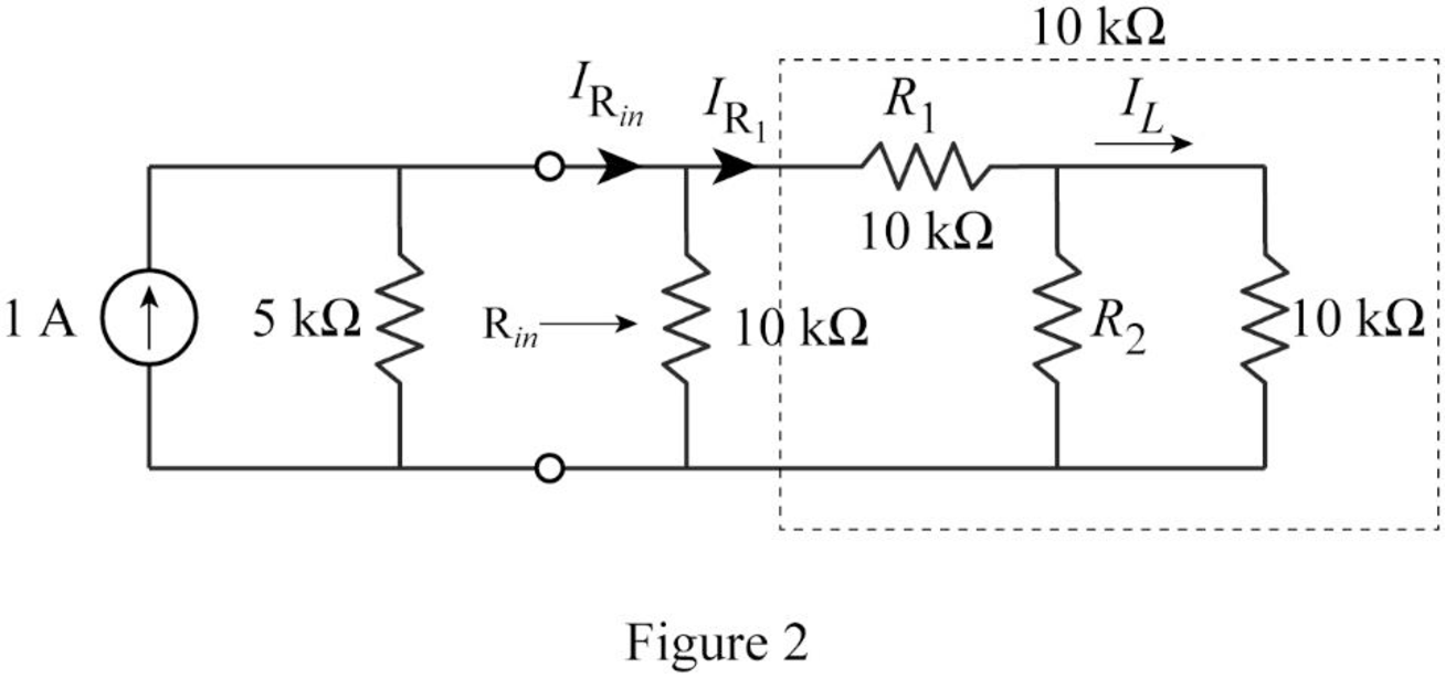
Therefore from current division rule, the current through
From current division rule, write the expression for current
Substitute
Rearrange the equation as follows.
Simplify the equation as follows.
Simplify the equation as follows.
Substitute
Simplify the equation as follows.
Simplify the equation to obtain the value of
Conclusion:
Thus, the values of
Want to see more full solutions like this?
Chapter 2 Solutions
Fundamentals of Electric Circuits


- At 300 K, an ideal solar cell has a short circuit current of 3A and an open circuit voltage of 0.6V. Calculate and sketch its power output as a function of operating voltage and find its fill factor from this power output.arrow_forwardA potentiometer consisting of a wire of length L0 has a source of emf, ɛ connected across it. When a standard cell with emf V = 6V, in series with a voltmeter, is connected at one end of the wire and at a distance L = 4 cm along the wire the voltmeter circuit is in balance and the voltmeter reads zero. When the standard cell is replaced by a source of unknown emf the new balance length is found to be 6 cm. What is the unknown emf? Select one: a. 9 V b. 8 V c. 4 V d. 3 Varrow_forwardWhen you are solving for circuit problems from the data obtained from experiments, what is the significance if you got a negative sign from a calculation? a. No significance B. It means you did something wrong on your calculation. C. Real resulting current or voltage is in the opposite direction to one assumed. D. You probably used smaller scaling factor. Explain ty.arrow_forward
- Finding the direction of the currents. Finding currents given that R2: 10.94 x 10^2 ohmR3: 9.89 x 10^2 ohmR4: 25 ohm Terminal Potential: Battery 1: 5 V using Kirchoff's laws. You will check some of the laws that govern electrical circuitsDirect current: conservation of current in a node, addition of potentialsfor series components, addition of currents for parallel componentsarrow_forwardThe values of the circuit elements are given below. accordingly, find the current i at t=34.6 sec.arrow_forward4/s2+6s+5 solve part barrow_forward
- identify the minterms that corresponds to the f and d below. Please be sure you know how to solve correctly and show work. I will also provide an image that states what the answer is without showing work I need to see work and explained how to get there. f=b'c'd' + abd' + abd d=a'c'd + b'cd'arrow_forward1. what is the total current of the circuit? a) 5.2143 A b) 1.0349 c) 1. 2329 d) 4,1428 2) What is the current at the 20-ohm resistor? a) 2A b) 0.397 A c) 1.5892 A d) 0.4729 A 3) what is the voltage drop across the 16-ohm resistor a) 58.0016 V b) 55.8624 V c) 47.0768 V d) 51.4288 Varrow_forwardNeed some help with this example. Also the nomenclature in this book is bad what exactly is P_n?arrow_forward
- 5) The switch, in the circuit below, is taken to position 2 at t=0. What is the value of i2 at t=34.7msec?arrow_forwardConsider a PV Module with 4 solar PV cells with the Size of each 10cm x 10cm are connected in Parallel. Choose the correct statement for the above PV Module. (Assume necessary data) a. The output voltage is 0.5 V, the output power is 12W b. The output voltage is 2 V, the output power is 12W c. The output voltage is 12 V, the output power is 6W d. The output voltage is 0.5 V, the output power is 6Warrow_forwardFind 8 ohm resistance current with Thevenin’s equivaleny circuit. please do. then explain to me thanksarrow_forward
 Introductory Circuit Analysis (13th Edition)Electrical EngineeringISBN:9780133923605Author:Robert L. BoylestadPublisher:PEARSON
 Delmar's Standard Textbook Of ElectricityElectrical EngineeringISBN:9781337900348Author:Stephen L. HermanPublisher:Cengage Learning
 Programmable Logic ControllersElectrical EngineeringISBN:9780073373843Author:Frank D. PetruzellaPublisher:McGraw-Hill Education
 Fundamentals of Electric CircuitsElectrical EngineeringISBN:9780078028229Author:Charles K Alexander, Matthew SadikuPublisher:McGraw-Hill Education
 Electric Circuits. (11th Edition)Electrical EngineeringISBN:9780134746968Author:James W. Nilsson, Susan RiedelPublisher:PEARSON
 Engineering ElectromagneticsElectrical EngineeringISBN:9780078028151Author:Hayt, William H. (william Hart), Jr, BUCK, John A.Publisher:Mcgraw-hill Education,